Power Up the Pi
To configure the Raspberry Pi for our purpose we will extend our Pi a little. This makes configuring and using the device easier and to be perfectly honest, making life hard for ourselves is so exhausting! Let’s not do that.
Static IP Address
As we mentioned earlier, enabling remote access is a really useful thing. This will allow us to configure and operate our Raspberry Pi from a separate computer. To do so we will want to assign our Raspberry Pi a static IP address.
The method by which a static address is assigned changed with the introduction of the operating system ‘bookworm’ (around the end of 2023). The older method used dhcpcd and the newer method uses nmcli. For the sake of completeness I will include both methods here.
An Internet Protocol address (IP address) is a numerical label assigned to each device (e.g., computer, printer) participating in a computer network that uses the Internet Protocol for communication.
There is a strong likelihood that our Raspberry Pi already has an IP address and it should appear a few lines above the ‘login’ prompt when you first boot up;
The My IP address... part should appear just above or around 15 lines above the login line, depending on the version of the Raspberry Pi OS we’re using. In this example the IP address 10.1.1.25 belongs to the Raspberry Pi.
This address will probably be a ‘dynamic’ IP address and could change each time the Pi is booted. For the purposes of using the Raspberry Pi with a degree of certainty when logging in to it remotely it’s easier to set a fixed IP address.
This description of setting up a static IP address makes the assumption that we have a device running on our network that is assigning IP addresses as required. This sounds complicated, but in fact it is a very common service to be running on even a small home network and most likely on an ADSL modem/router or similar. This function is run as a service called DHCP (Dynamic Host Configuration Protocol). You will need to have access to this device for the purposes of knowing what the allowable ranges are for a static IP address.
The Netmask
A common feature for home modems and routers that run DHCP devices is to allow the user to set up the range of allowable network addresses that can exist on the network. At a higher level we should be able to set a ‘netmask’ which will do the job for us. A netmask looks similar to an IP address, but it allows you to specify the range of addresses for ‘hosts’ (in our case computers) that can be connected to the network.
A very common netmask is 255.255.255.0 which means that the network in question can have any one of the combinations where the final number in the IP address varies. In other words with a netmask of 255.255.255.0, the IP addresses available for devices on the network ‘10.1.1.x’ range from 10.1.1.0 to 10.1.1.255 or in other words any one of 256 unique addresses.
CIDR Notation
An alternative to specifying a netmask in the format of ‘255.255.255.0’ is to use a system called Classless Inter-Domain Routing, or CIDR. The idea is to add a specification in the IP address itself that indicates the number of significant bits that make up the netmask.
For example, we could designate the IP address 10.1.1.17 as associated with the netmask 255.255.255.0 by using the CIDR notation of 10.1.1.17/24. This means that the first 24 bits of the IP address given are considered significant for the network routing.
Using CIDR notation allows us to do some very clever things to organise our network, but at the same time it can have the effect of confusing people by introducing a pretty complex topic when all they want to do is get their network going :-). So for the sake of this explanation we can assume that if we wanted to specify an IP address and a netmask, it could be accomplished by either specifying each separately (IP address = 10.1.1.17 and netmask = 255.255.255.0) or in CIDR format (10.1.1.17/24)
Distinguish Dynamic from Static
The other service that our DHCP server will allow is the setting of a range of addresses that can be assigned dynamically. In other words we will be able to declare that the range from 10.1.1.20 to 10.1.1.255 can be dynamically assigned which leaves 10.1.1.0 to 10.1.1.19 which can be set as static addresses.
You might also be able to reserve an IP address on your modem / router. To do this you will need to know what the MAC (or hardware address) of the Raspberry Pi is. To find the hardware address on the Raspberry Pi type;
(For more information on the ifconfig command check out the Linux commands section)
This will produce an output which will look a little like the following;
The figures b8:27:eb:b6:2e:da are the Hardware or MAC address.
Because there are a huge range of different DHCP servers being run on different home networks, I will have to leave you with those descriptions and the advice to consult your devices manual to help you find an IP address that can be assigned as a static address. Make sure that the assigned number has not already been taken by another device. In a perfect World we would hold a list of any devices which have static addresses so that our Pi’s address does not clash with any other device.
For the sake of the upcoming project we will assume that the address 10.1.1.110 is available.
Default Gateway
Before we start configuring we will need to find out what the default gateway is for our network. A default gateway is an IP address that a device (typically a router) will use when it is asked to go to an address that it doesn’t immediately recognise. This would most commonly occur when a computer on a home network wants to contact a computer on the Internet. The default gateway is therefore typically the address of the modem / router on your home network.
We can check to find out what our default gateway is from Windows by going to the command prompt (Start > Accessories > Command Prompt) and typing;
This should present a range of information including a section that looks a little like the following;
The default router gateway is therefore ‘10.1.1.1’.
For OS’s Prior to bookworm
Lets edit the dhcpcd.conf file
On the Raspberry Pi at the command line we are going to start up a text editor and edit the file that holds the configuration details for the network connections.
The file is /etc/dhcpcd.conf. That is to say it’s the dhcpcd.conf file which is in the etc directory which is in the root (/) directory.
To edit this file we are going to type in the following command;
The nano file editor will start and show the contents of the dhcpcd.conf file which should look a little like the following;
for dhcpcd.
# See dhcpcd.conf(5) for details.
# Allow users of this group to interact with dhcpcd via the control socket.
#controlgroup wheel
# Inform the DHCP server of our hostname for DDNS.
hostname
# Use the hardware address of the interface for the Client ID.
clientid
# or
# Use the same DUID + IAID as set in DHCPv6 for DHCPv4 ClientID per RFC4361.
#duid
# Persist interface configuration when dhcpcd exits.
persistent
# Rapid commit support.
# Safe to enable by default because it requires the equivalent option set
# on the server to actually work.
option rapid_commit
# A list of options to request from the DHCP server.
option domain_name_servers, domain_name, domain_search, host_name
option classless_static_routes
# Most distributions have NTP support.
option ntp_servers
# Respect the network MTU. This is applied to DHCP routes.
option interface_mtu
# A ServerID is required by RFC2131.
require dhcp_server_identifier
# Generate Stable Private IPv6 Addresses instead of hardware based ones
slaac private
# Example static IP configuration:
#interface eth0
#static ip_address=192.168.0.10/24
#static ip6_address=fd51:42f8:caae:d92e::ff/64
#static routers=192.168.0.1
#static domain_name_servers=192.168.0.1 8.8.8.8 fd51:42f8:caae:d92e::1
# It is possible to fall back to a static IP if DHCP fails:
# define static profile
#profile static_eth0
#static ip_address=192.168.1.23/24
#static routers=192.168.1.1
#static domain_name_servers=192.168.1.1
# fallback to static profile on eth0
#interface eth0
#fallback static_eth0
The file actually contains some commented out sections that provide guidance on entering the correct configuration.
We are going to add the information that tells the network interface to use eth0 at our static address that we decided on earlier (10.1.1.110) along with information on the netmask to use (in CIDR format) and the default gateway of our router. To do this we will add the following lines to the end of the information in the dhcpcd.conf file;
Here we can see the IP address and netmask (static ip_address=10.1.1.110/24), the gateway address for our router (static routers=10.1.1.1) and the address where the computer can also find DNS information (static domain_name_servers=10.1.1.1).
Once you have finished press ctrl-x to tell nano you’re finished and it will prompt you to confirm saving the file. Check your changes over and then press ‘y’ to save the file (if it’s correct). It will then prompt you for the file-name to save the file as. Press return to accept the default of the current name and you’re done!
To allow the changes to become operative we can type in;
This will reboot the Raspberry Pi and we should see the (by now familiar) scroll of text and when it finishes rebooting you should see;
Which tells us that the changes have been successful (bearing in mind that the IP address above should be the one you have chosen, not necessarily the one we have been using as an example).
For OS’s From bookworm onward
From late 2023 on (assuming that you’re using the latest available Operating System), the default command line tool for setting a static IP address changed to nmcli (nccli is the command line interface tool for the NetworkManager package.
Using this tool means that there is no editing of configuration files required.
To find the name of the connection that we are going to change we run the nmcli con show command. (this is basically shorthand for saying “Show the connections nmcli!”.
This will produce something like the following;
From our checking we know that;
-
Wired connection 1is the name of the connection that we will be setting to a static IP address -
10.1.1.110/24is the static IP address and the netmask that we want (in CIDR notation) -
10.1.1.1is our gateway -
10.1.1.1is also our the address where the computer can go to find DNS information.
Now we can run the commands that will set the Static IP address with all our desired parameters as follows;
We could have actually strung all those commands together as a single command, but for the sake of formatting in the book, the above avoids confusion with line breaks.
To save the changes and reload the network manager we run the following command;
All that remains is to reboot the Pi for the changes to take effect;
This will reboot the Raspberry Pi and we should see the (by now familiar) scroll of text and when it finishes rebooting you should see;
Which tells us that the changes have been successful (bearing in mind that the IP address above should be the one you have chosen, not necessarily the one we have been using as an example).
Remote access
To allow us to work on our Raspberry Pi from our normal desktop we can give ourselves the ability to connect to the Pi from another computer. The will mean that we don’t need to have the keyboard / mouse or video connected to the Raspberry Pi and we can physically place it somewhere else and still work on it without problem. This process is called ‘remotely accessing’ our computer .
To do this we need to install an application on our windows desktop which will act as a ‘client’ in the process and have software on our Raspberry Pi to act as the ‘server’. There are a couple of different ways that we can accomplish this task, but because we will be working at the command line (where all we do is type in our commands (like when we first log into the Pi)) we will use what’s called SSH access in a ‘shell’.
Remote access via SSH
Secure SHell (SSH) is a network protocol that allows secure data communication, remote command-line login, remote command execution, and other secure network services between two networked computers. It connects, via a secure channel over an insecure network, a server and a client running SSH server and SSH client programs, respectively (there’s the client-server model again).
In our case the SSH program on the server is running sshd and on the Windows machine we will use a program called ‘PuTTY’.
Setting up the Server (Raspberry Pi)
SSH is already installed and operating but to check that it is there and working type the following from the command line;
The Pi should respond with the message that the program sshd is active (running).
(/lib/systemd/system/ssh.service; enabled)
Active: active (running) since Tue 2017-04-25 03:30:16 UTC; 1h 28min ago
Main PID: 2135 (sshd)
CGroup: /system.slice/ssh.service
└─2135 /usr/sbin/sshd -D
If it isn’t, run the following command;
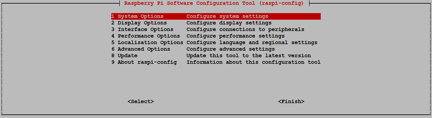
Use the up and down arrow keys to move the highlighted section to the selection you want to make then press tab to highlight the <Select> option (or <Finish> if you’ve finished).
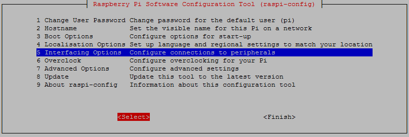
To enable SSH select ‘5 Interfacing Options’ from the main menu.
From here we select ‘P2 SSH’
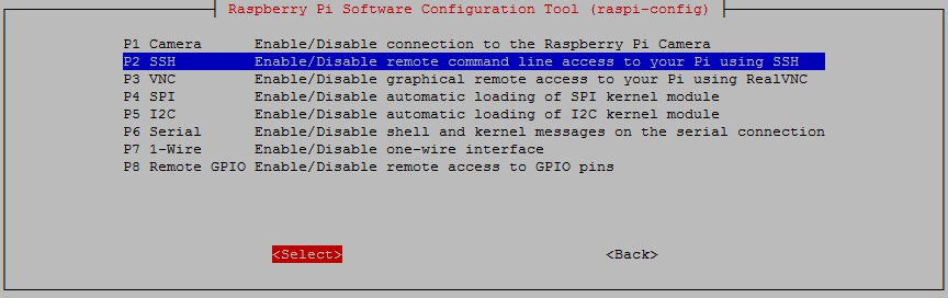
And we should be done!
Setting up the Client (Windows)
The client software we will use is called ‘Putty’. It is open source and available for download from here.
On the download page there are a range of options available for use. The best option for us is most likely under the ‘For Windows on Intel x86’ heading and we should just download the ‘putty.exe’ program.
Save the file somewhere logical as it is a stand-alone program that will run when you double click on it (you can make life easier by placing a short-cut on the desktop).
Once we have the file saved, run the program by double clicking on it and it will start without problem.
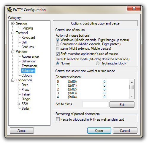
The first thing we will set-up for our connection is the way that the program recognises how the mouse works. In the ‘Window’ Category on the left of the PuTTY Configuration box, click on the ‘Selection’ option. On this page we want to change the ‘Action of mouse’ option from the default of ‘Compromise (Middle extends, Right paste)’ to ‘Windows (Middle extends, Right brings up menu)’. This keeps the standard Windows mouse actions the same when you use PuTTY.
Now select the ‘Session’ Category on the left hand menu. Here we want to enter our static IP address that we set up earlier (10.1.1.160 in the example that we have been following, but use your one) and because we would like to access this connection on a frequent basis we can enter a name for it as a saved session (In the screen-shot below it is imaginatively called ‘Raspberry Pi’). Then click on ‘Save’.
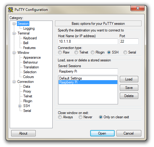
Now we can select our Raspberry Pi session (per the screen-shot above) and click on the ‘Open’ button.
The first thing you will be greeted with is a window asking if you trust the host that you’re trying to connect to.
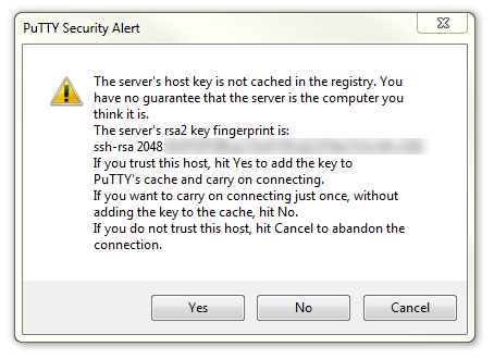
In this case it is a pretty safe bet to click on the ‘Yes’ button to confirm that we know and trust the connection.
Once this is done, a new terminal window will be shown with a prompt to login as: . Here we can enter our user name (‘pi’) and then our password (if it’s still the default, the password is ‘raspberry’).
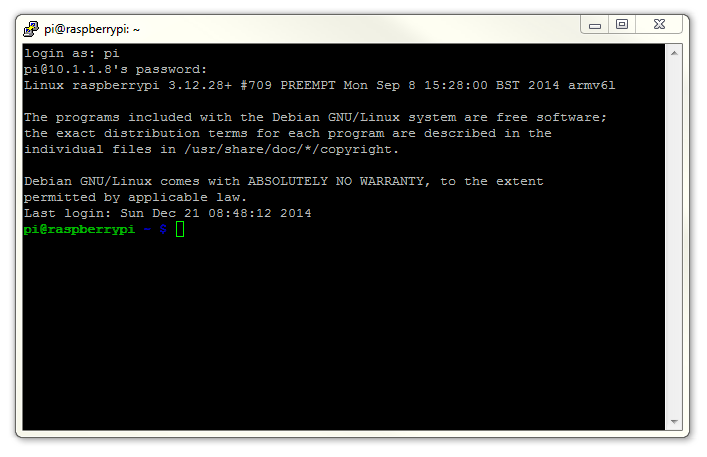
There you have it. A command line connection via SSH. Well done.
WinSCP
To make the process of transferring files from Windows easier I would recommend looking to the program WinSCP. (If you’re using Linux I will make the assumption that you know how to do the equivalent using SCP.)
This provides a very intuitive way to copy files between your desktop and the Pi.
Download and install the program. Once installed, click on the desktop icon.
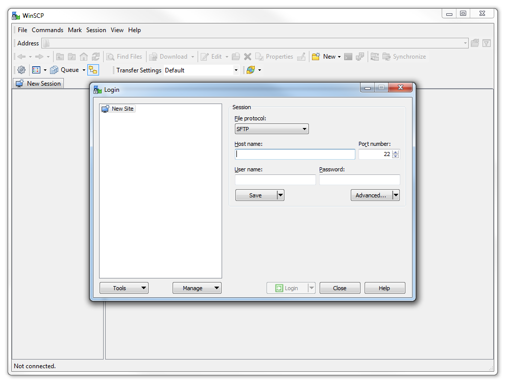
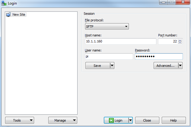
The program opens with default login page. Enter the ‘Host name’ field with the IP address of the Pi. Also put in the username and password of the Pi.
Click on ‘Save’ to save the login details for ease of future access.
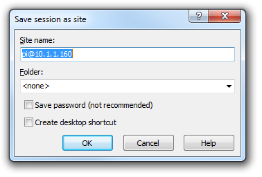
Enter the ‘Site name’ as a name of the Pi or leave it as the default, with the user and IP address. Check the ‘Save password’ for a convenient but insecure way to avoid typing in the username and password in the future. Then press OK
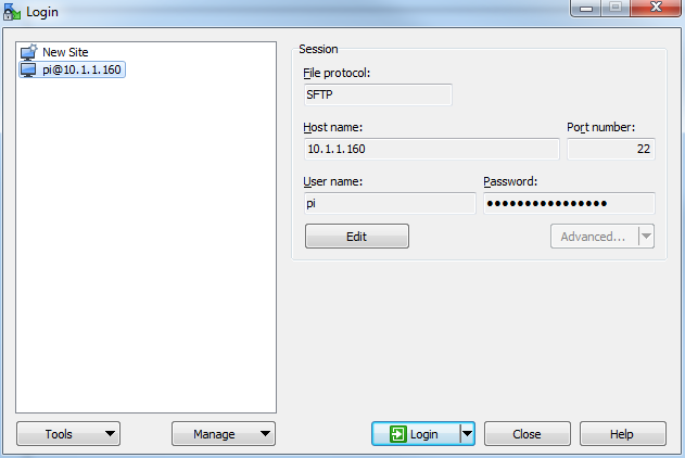
The saved login details now appear on the left hand pane. Click on ‘Login’ to log in to the Pi.
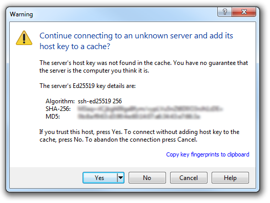
We will receive a warning about connecting to an unknown server for the first time. Assuming that we are comfortable doing this (i.e. that we know that we are connecting the Pi correctly) we can click on ‘Yes’.
There is a possibility that it might fail on its first attempt, but tell it to reconnect if it does and we should be in!
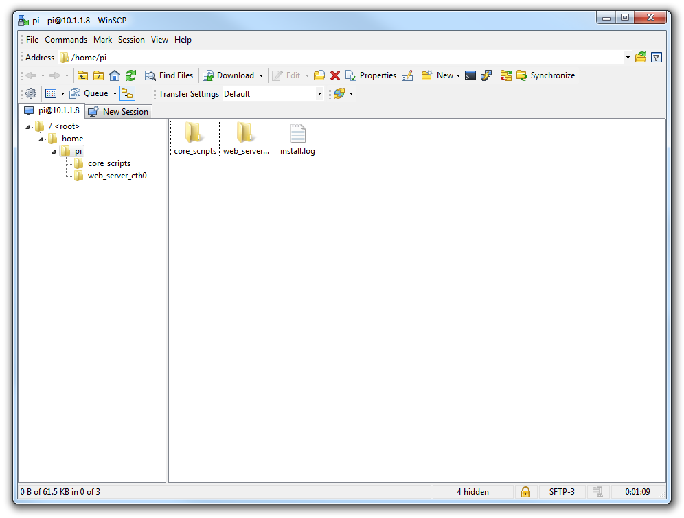
Here we can see a familiar tree structure for file management and we have the ability to copy files via dragging and dropping them into place.
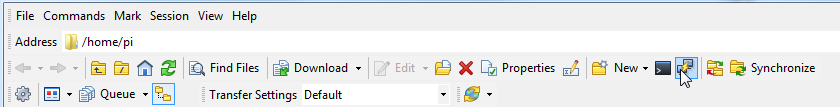
Assuming that we already have PuTTY installed we should be able to click on the ‘Open Session in PuTTY’ icon and we will get access to the command line.
If this is the first time that you’ve done something like this (remotely accessing a computer) it can be a very liberating feeling. Nice job.
Setting up a WiFi Network Connection
Our set-up of the Raspberry Pi will allow us to carry out all the (computer interface) interactions via a remote connection. However, the Raspberry Pi is currently making that remote connection via a fixed network cable. It could be argued that the lower number of connections that we need to run to our machine the better. The most obvious solution to this conundrum is to enable a wireless connection.
It should be noted that enabling a wireless network will not be a requirement for everyone, and as such, I would only recommend it if you need to. If you’re using a model B3, B3+, 4, 5, Zero W or Zero 2W you have WiFi built in, otherwise you will need to purchase a USB WiFi dongle and correctly configure it.
We should also note that the configuration of your WiFi connection can be set using the Raspberry Pi Imager as mentioned earlier in the book.
Built in WiFi Enabling
We need to edit the file wpa_supplicant.conf at /etc/wpa_supplicant/wpa_supplicant.conf. This looks like the following;
Use the nano command as follows;
We need to add the ssid (the wireless network name) and the password for the WiFi network here so that the file looks as follows (using your ssid and password of course);
Make the changes operative
To allow the changes to become operative we can type in;
Once we have rebooted, we can check the status of our network interfaces by typing in;
This will display the configuration for our wired Ethernet port, our ‘Local Loopback’ (which is a fancy way of saying a network connection for the machine that you’re using, that doesn’t require an actual network (ignore it in the mean time)) and the wlan0 connection which should look a little like this;
flags=4163<UP,BROADCAST,RUNNING,MULTICAST> mtu 1500
inet 10.1.1.99 netmask 255.255.255.0 broadcast 10.1.1.255
inet6 fe80::8b9f:3e4f:dcf0:12a9 prefixlen 64 scopeid 0x20<link>
ether b8:27:eb:e3:b7:f2 txqueuelen 1000 (Ethernet)
RX packets 51 bytes 9384 (9.1 KiB)
RX errors 0 dropped 0 overruns 0 frame 0
TX packets 35 bytes 6078 (5.9 KiB)
TX errors 0 dropped 0 overruns 0 carrier 0 collisions 0
This would indicate that our wireless connection has been assigned the dynamic IP address 10.1.1.99.
We should be able to test our connection by connecting to the Pi via SSH and ‘PuTTY’ on the Windows desktop using the address 10.1.1.99.
In theory you are now the proud owner of a computer that can be operated entirely separate from all connections except power!
Make the built in WiFi IP address static
In the same way that we would edit the /etc/dhcpcd.conf file to set up a static IP address for our physical connection (eth0) we will now edit it with the command…
This time we will add the details for the wlan0 connection to the end of the file. Those details (assuming we will use the 10.1.1.17 IP address) should look like the following;
Our wireless lan (wlan0) is now designated to be a static IP address (with the details that we had previously assigned to our wired connection) and we have added the ‘ssid’ (the network name) of the network that we are going to connect to and the password for the network.
Make the changes operative
To allow the changes to become operative we can type in;
We’re done!
WiFi Via USB Dongle
Using an external USB WiFi dongle can be something of an exercise if not done right. In my own experience, I found that choosing the right wireless adapter was the key to making the job simple enough to be able to recommend it to new users. Not all WiFi adapters are well supported and if you are unfamiliar with the process of installing drivers or compiling code, then I would recommend that you opt for an adapter that is supported and will work ‘out of the box’. There is an excellent page on elinux.org which lists different adapters and their requirements. I eventually opted for the Edimax EW-7811Un which literally ‘just worked’ and I would recommend it to others for it’s ease of use and relatively low cost (approximately $15 US).

To install the wireless adapter we should start with the Pi powered off and install it into a convenient USB connection. When we turn the power on we will see the normal range of messages scroll by, but if we’re observant we will note that there are a few additional lines concerning a USB device. These lines will most likely scroll past, but once the device has finished powering up and we have logged in we can type in…
… which will show us a range of messages about drivers that are loaded to support discovered hardware.
Somewhere in that list (hopefully towards the end) will be a series of messages that describe the USB connectors and what is connected to them. In particular we could see a group that looks a little like the following;
That is our USB adapter which is plugged into USB slot 2 (which is the ‘2’ in usb 1-1.2:). The manufacturer is listed as ‘Realtek’ as this is the manufacturer of the chip-set in the adapter that Edimax uses.
Editing files
We need to edit two files. The first is the file wpa_supplicant.conf at /etc/wpa_supplicant/wpa_supplicant.conf. This looks like the following;
Use the nano command as follows;
We need to add the ssid (the wireless network name) and the password for the WiFi network here so that the file looks as follows (using your ssid and password of course);
Make the changes operative
To allow the changes to become operative we can type in;
Once we have rebooted, we can check the status of our network interfaces by typing in;
This will display the configuration for our wired Ethernet port, our ‘Local Loopback’ (which is a fancy way of saying a network connection for the machine that you’re using, that doesn’t require an actual network (ignore it in the mean time)) and the wlan1 connection which should look a little like this;
flags=4163<UP,BROADCAST,RUNNING,MULTICAST> mtu 1500
inet 10.1.1.97 netmask 255.255.255.0 broadcast 10.1.1.255
inet6 fe80::c4e4:a6e5:9788:d2c2 prefixlen 64 scopeid 0x20<link>
ether 00:ec:0b:4c:6b:99 txqueuelen 1000 (Ethernet)
RX packets 106 bytes 18616 (18.1 KiB)
RX errors 0 dropped 0 overruns 0 frame 0
TX packets 34 bytes 5681 (5.5 KiB)
TX errors 0 dropped 0 overruns 0 carrier 0 collisions 0
This would indicate that our wireless connection has been assigned the dynamic IP address 10.1.1.97.
We should be able to test our connection by connecting to the Pi via SSH and ‘PuTTY’ on the Windows desktop using the address 10.1.1.97.
Make USB WiFi IP address static
In the same way that we would edit the /etc/dhcpcd.conf file to set up a static IP address for our physical connection (eth0) we will now edit it with the command…
This time we will add the details for the wlan1 connection to the end of the file. Those details (assuming we will use the 10.1.1.110 IP address) should look like the following;
Make the changes operative
To allow the changes to become operative we can type in;
We’re done!