Chapter 7 - Physical Computing with Raspberry Pi
“The role of the teacher is to create the conditions for invention rather than provide ready-made knowledge.”
–Seymour Papert
What is Physical Computing?
The GPIO (General Purpose Input Output) pins allow the Raspberry Pi to control and monitor the outside world through electronic circuits. The Pi is able to control LEDs - turning them on or off - run motors, and many other things. It’s also able to detect whether a switch has been pressed, the temperature inside a room, or light levels. In simple terms, you can think of the GPIO pins as switches that you can turn on or off (input) or that the Pi can turn on or off (output). We refer to this ability as physical computing. Physical computing is a great way to get your students started with building, thinking, and creating with the Raspberry Pi. Programming can be fun and engaging for some students, but many students want to build something tangible. Physical computing provides the opportunity for both coding and building. Additionally, physical computing can fit nicely into project-based learning units, as it allows for “Do-It-Together” (DIT) methods of instruction. Students can work in groups with assigned roles such as designer, coder/programmer, engineer/builder, project manager, evaluator, etc. This type of learning simulates real-world teams and can help students connect skills (technical and non-cognitive) learned in the classroom to future careers. Finally, physical computing is a great introduction to the Internet of Things (IoT) projects. Learn more about IoT and the Raspberry Pi in Chapter 10.
Physical Computing w/ Scratch
Scratch is generally the easiest language to use when getting started with physical computing projects. As you saw in Chapter 5, Scratch is an easy-to-use, “drag-and-drop” programming language designed for new learners. Physical computing can often become quickly complex since you are now having to write code AND design a circuit or assembly some type of hardware. Often new learners will have the circuit wired correctly, but the code is wrong. Simplifying the code for physical computing projects helps new learners focus on the logic and problem-solving skills needed to be build their circuits successfully. Once learners are comfortable with circuit building, they can then move to Python coding, which offers greater flexibility and opportunities for advanced physical computing projects.
Project #1 - LEDs and Buttons
Physical Computing With Scratch by the Raspberry Pi Foundation is licensed under a Creative Commons Attribution 4.0 International Licence
WARNING: If you follow the instructions, then playing about with the GPIO pins is safe and fun. Randomly plugging wires and power sources into your Pi, however, may destroy it, especially if using the 5V pins. Bad things can also happen if you try to connect things to your Pi that use a lot of power; LEDs are fine, high-voltage motors are not. If you’re worried about this, then you might want to consider using an add-on board such as the Explorer HAT until you’re confident enough to use the GPIO directly.
GPIO pins
There are 40 pins on the Raspberry Pi (26 pins on early models), and they provide various different functions.
This guide can help you to identify the pin numbers:
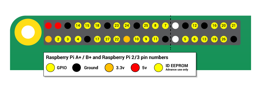
You’ll see pins labelled as 3V3, 5V, GND and GP2, GP3, etc:
| 3V3 | 3.3 volts | Anything connected to these pins will always get 3.3V of power |
| 5V | 5 volts | Anything connected to these pins will always get 5V of power |
| GND | ground | Zero volts, used to complete a circuit |
| GP2 | GPIO pin 2 | These pins are for general-purpose use and can be configured as input or output pins |
| ID_SC/ID_SD/DNC | Special purpose pins |
Lighting an LED
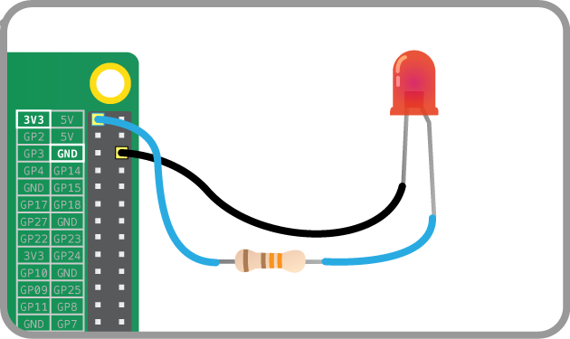
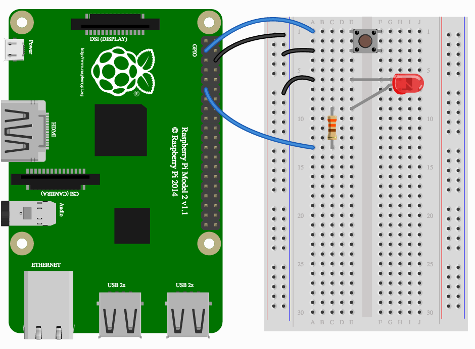
You can test whether your GPIO pins and LEDs are working by building the circuit below.
- The LED is connected directly to the 3.3V and GND pins, and should light up.
- Be sure to connect your LED the correct way round; the longer leg should be connected to the 3V3 pin:
Using a switchable pin
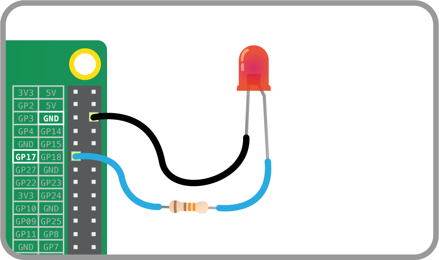
- To control the LED, you’ll need to adapt your circuit to use a switchable pin.
- In the diagram below pin 17 has been used, but you can use any numbered pin you wish.
Constructing a Scratch program
- Locate the Scratch program by clicking on Menu followed by Programming, and selecting Scratch.
- The familiar Scratch interface will then load.
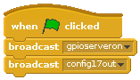
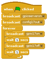
- Click on Control in the top-left display. Drag the
when GreenFlag clickedblock onto the scripts area:

- Scratch uses broadcast blocks to communicate with the GPIO pins; the first broadcast you need is
gpioserveronwhich activates the GPIO functionality:

- As your GPIO pin can be used as either input or output, you’ll need to specify in which mode your pin is being used with the
config17outbroadcast:
- From this point on, you can control your LED using two broadcasts:
gpio17highto turn it on andgpio17lowto turn it off. Using these two messages and some pauses, you can make an LED flash continuously:
Connecting a button
- As well as controlling the physical world, you can react to it using an input device such as a button.
- Connect your button to a breadboard, then connect one pin to a ground pin and the other to a numbered GPIO pin. In this example pin 2 has been used. Make a circuit like this:
Configuring your button
- Before Scratch can react to your button, it needs to be told which pin is configured as an input pin.
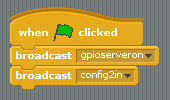
- Assuming you have started a new Scratch file, you’ll also need to start the GPIO server. The following code will configure pin 4 as an input:
- Once you have built the code above, you need to click the green flag in order for it to run and for your pin to be set up.
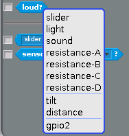
- Next, you need to go to the Sensing menu in Scratch:

- From here you need to find the
 block and click the triangle to reveal a menu. Select gpio2 from the menu and click the tickbox to the left:
- You should now see the current state of the pin in the stage area:
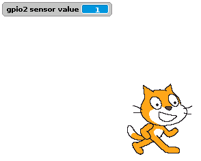
- Now when you press your button, the state should change from 1 to 0.
Responding to a button press
- Now that your button is all set up and working, you can make it do something. You can start off by making it control a sprite.
- Begin with a
foreverloop with anifblock inside it. This will continually check theifcondition and perform some action if the condition is met. The action in the example below will make the current sprite move forward: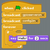
Loop with condition - Finally, to make this work you need to add the condition, which is that we want the move action to happen when the button value = 0:
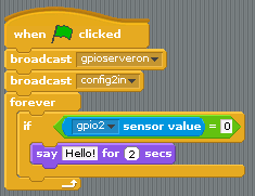
Complete Code
If everything is correct, your button should make the sprite move.
Controlling an LED with a button push
To finish off, you can combine your two programs so that the button can turn the LED on and off.
- Adapt your script and use an
If Elseblock so that it looks like the example below: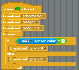
Complete code - Now when you push the button, the LED should light up.
Project #2 - Santa Detector
Santa Detector by the Raspberry Pi Foundation is licensed under a Creative Commons Attribution 4.0 International Licence
You will build a detector that spots any movement and sets off an alarm. Along the way, you will learn how to connect a passive infra-red (PIR) sensor to the Raspberry Pi, and how to control the flow of your Scratch program by responding to the input from the sensor.
Connect the PIR motion sensor
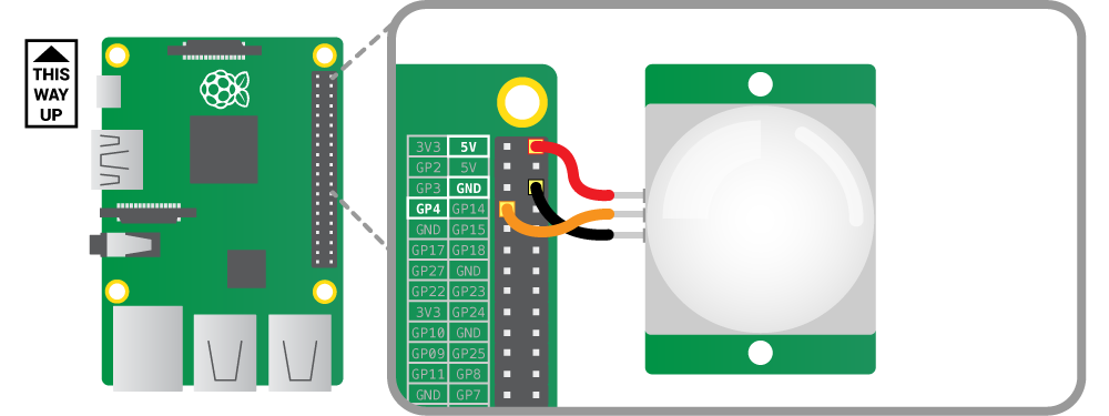
Before booting your Raspberry Pi, connect the PIR module to the Raspberry Pi.
Using three female-to-female jumper cables, you’ll need to connect each of the PIR sensor’s connectors to the appropriate pins on the Raspberry Pi.
Connect the top one labelled VCC on the PIR sensor to the 5V pin on the Raspberry Pi, connect the middle one labelled OUT to GPIO pin 4, and connect the bottom one labelled GND to a ground pin also marked GND. All shown in the following diagram:
Test the sensor
Because we are using the GPIO pins, we need to start the GPIO server in Scratch:
- On the desktop run Scratch using
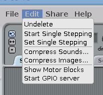
Menu -> Programming -> Scratch. - Once Scratch is running choose
Start GPIO Serverfrom theEditmenu.
Scratch uses the ‘Sensing’ blocks to check if there is any input on the GPIO pins. If there is an input, the value of the pin changes from 0 to 1. As you connected the PIR sensor to GPIO pin 4 of the Pi, we need to monitor that.
Firstly we need to tell Scratch that pin 4 will be used as an input by configuring it.
- Create a broadcast message as follows:

- Double click the broadcast block to run it. You only need to do this once.
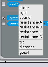
- In the
Sensingblock palette click on the drop-down menu on thesensor valueblock and choosegpio4. - Tick the check-box to the left of the block to display the pin value on screen.
NOTE: If you do not see gpio4 on the list, make sure that the GPIO server is running and that you have run the config broadcast.
Test the PIR sensor by waving your hand in front of it. When it detects movement, the value on the screen should change from 0 to 1.
If the value doesn’t change, check that the correct pins are connected.
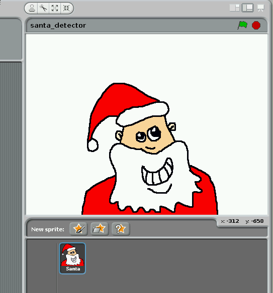
Draw a sprite and add sound
Click on the ‘Costumes’ tab and draw (or use the one below) a Santa sprite This will be displayed when the PIR senses movement.

Click on the ‘Sounds’ tab and import a sound from the ‘Electronic’ folder. I’ve used a siren called ‘Whoop’ here.
Program what happens when the detector spots movement
Now we have a sensor that reports when it is on or off, we can use this value to control the flow of our program.
Build the following script:
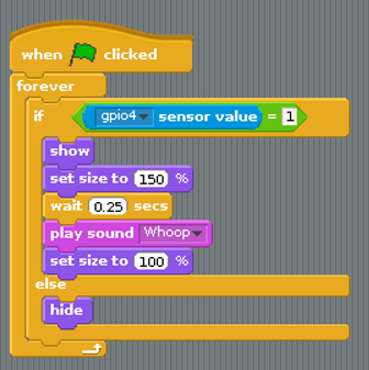
What is the the program doing?
The if statement continuously checks the pin 7 sensor value. When this changes to 1 it does the following:
- shows the sprite
- makes the sprite bigger
- waits a bit
- plays a sound
- makes the sprite normal size
It keeps doing this as long as the sensor value is 1 i.e. when the PIR detects movement.
The else statement simply hides the sprite when the sensor value is 0.
Set up the detector in your room!
- On Christmas Eve, set up your Pi with the sensor pointing at your bedroom door.
- Connect your Pi to a huge speaker.
- Make sure the sensor does not detect you in bed or you will get false positives; the alarm will go off every time you move!
- Go to sleep.
- Wake up when Santa comes in and feed him mince pies and sherry.
Physical Computing w/ Python
Python is great for more advanced physical computing projects. Ben Nuttall has created a easy-to-use application programming interface (API) for accessing the GPIO pins via Python called GPIO Zero. GPIO Zero is a Python library which provides a simple interface to everyday GPIO components. It comes installed by default in Raspbian.
Project #1 - LEDs and Buttons
Physical Computing With Python by the Raspberry Pi Foundation is licensed under a Creative Commons Attribution 4.0 International Licence
GPIO pins
WARNING: If you follow the instructions, then playing about with the GPIO pins is safe and fun. Randomly plugging wires and power sources into your Pi, however, may destroy it, especially if using the 5V pins. Bad things can also happen if you try to connect things to your Pi that use a lot of power; LEDs are fine, high-voltage motors are not. If you’re worried about this, then you might want to consider using an add-on board such as the Explorer HAT until you’re confident enough to use the GPIO directly.
Lighting an LED
LEDs are delicate little things. If you put too much current through them they will pop (sometimes quite spectacularly). To limit the current going through the LED, you should always use a resistor in series with it.
Try connecting an LED to the Pi’s 3V3 and GND pins with a resistor. Anything over about 50ç«‹ should do the trick:
The LED should light up. It will always be on, because it’s connected to a 3V3 pin, which is itself always on.
Now try moving it from 3V3 to GPIO pin 17:
The LED should now turn off, but now it’s on a GPIO pin, and can therefore be controlled by code.
Switching an LED on and off
- Open IDLE from the main menu (
Menu>Programming>Python 3 (IDLE). - You can switch an LED on and off by typing commands directly into the Python interpreter window (also known as the Python shell). Let’s do this by first importing the GPIO Zero library. You also need to tell the Pi which GPIO pin you are using - in this case pin 17. Next to the chevrons
>>>, type:1fromgpiozeroimportLED2led=LED(17)Press Enter on the keyboard.
- To make the LED switch on, type the following and press Enter:
1led.on() - To make it switch off you can type:
1led.off() - Your LED should switch on and then off again. But that’s not all you can do.
Flashing an LED
With the help of the time library and a little loop, you can make the LED flash.
- Create a new file by clicking File > New file.
- Save the new file by clicking File > Save. Save the file as
gpio_led.py. - Enter the following code to get started:
1fromgpiozeroimportLED2fromtimeimportsleep34led=LED(17)56whileTrue:7led.on()8sleep(1)9led.off()10sleep(1) - Save with Ctrl + S and run the code with F5.
- The LED should be flashing on and off. To exit the program press Ctrl + C on your keyboard.
Using buttons to get input
Now you’re able to control an output component (an LED), let’s connect and control an input component: a button.
- Connect a button to another GND pin and GPIO pin 2. Your circuit should now look like this:
- Create a new file by clicking File > New file.
- Save the new file by clicking File > Save. Save the file as
gpio_button.py. - This time you’ll need the
Buttonclass, and to tell it that the button is on pin 2. Write the following code in your new file:1fromgpiozeroimportButton2button=Button(2) - Now you can get your program to do something when the button is pushed. Add these lines:
1button.wait_for_press()2print('You pushed me') - Save with Ctrl + S and run the code with F5.
- Press the button and your text will appear.
Manually controlling the LED
You can now combine your two programs written so far to control the LED using the button.
- Create a new file by clicking File > New file.
- Save the new file by clicking File > Save. Save the file as
gpio_control.py. - Now write the following code:
1fromgpiozeroimportLED,Button2fromtimeimportsleep34led=LED(17)5button=Button(2)67button.wait_for_press()8led.on()9sleep(3)10led.off() - Save and run your program. When you push the button the LED should come on for three seconds.
Making a switch
With a switch, a single press and release on the button would turn the LED on, and another press and release would turn it off again.
- Modify your code so that it looks like this:
1fromgpiozeroimportLED,Button2fromtimeimportsleep34led=LED(17)5button=Button(2)67whileTrue:8button.wait_for_press()9led.toggle()led.toggle()switches the state of the LED from on to off, or off to on. Since this happens in a loop the LED with turn on and off each time the button is pressed. - It would be great if you could make the LED switch on only when the button is being held down. With GPIO Zero, that’s easy. There are two methods of the
Buttonclass calledwhen_pressedandwhen_released. These don’t block the flow of the program, so if they are placed in a loop, the program will continue to cycle indefinitely. - Modify your code to look like this:
1fromgpiozeroimportLED,Button2fromsignalimportpause34led=LED(17)5button=Button(2)67button.when_pressed=led.on8button.when_released=led.off910pause() - Save and run the program. Now when the button is pressed, the LED will light up. It will turn off again when the button is released.
Project #2 - Quick Reaction Game
Quick Reaction Game by the Raspberry Pi Foundation is licensed under a Creative Commons Attribution 4.0 International Licence
In this project, you’re going to make a quick reaction game using a few electronic components and a Python script.
Building the circuit
This is the circuit you are going to build, consisting of two push-to-make buttons and an LED.
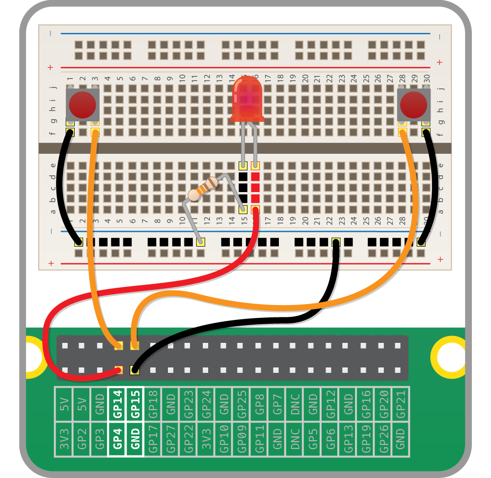
- Take one of your tactile buttons and push it into the holes on your breadboard, with one set of legs on row
Hand one set of legs on rowJ. - Repeat the last step with the second button, placing it at the other end of the breadboard on the same row.
- Place an LED with the longer leg above the ridge in the breadboard in
D16and the shorter leg inD15. The numbering will depend on your breadboard so make sure that you check the diagram below. - Next push one leg of the resistor into the same column
15as the short leg of the resistor and the other leg into a hole along the blue strip. - Now it’s time to add the jumper wires. Start by taking two male-to-male jumper wires and placing one end in a hole next to the outside leg of the left hand button, and the other end in a hole along the blue strip. Repeat this step with the right hand button.
- Then with a male-to-female jumper wire, connect GPIO14 to a hole on the breadboard in line with the other leg of the left hand button. Repeat this step for the right hand button, only this time connecting it to GPIO15.
- Using another male-to-female jumper wire, connect GPIO4 to a hole on the breadboard in line with the long leg of the LED.
- Finally, connect a GND GPIO pin to the blue strip on the breadboard with the remaining male-to-female jumper wire.
Controlling the light
When programming, it makes sense to tackle one problem at a time. This makes it easier to test your project at various stages.
- Click on the
Menu>Programming>Python 3 (IDLE) - Create a new text editor file by clicking on
File>New File - Save this file as reaction.py by clicking on
File>Save As - First you will need to import the modules and libraries needed to control the GPIO pins on the Raspberry Pi. Type:
1fromgpiozeroimportLED,Button2fromtimeimportsleep - As you are outputting to an LED, you need to set up the pin that the LED connects to on the Raspberry Pi as an output. First use a variable to name the pin and then set the output:
1led=LED(4) - Next add a line to turn the LED on:
1led.on() - Now add a line to wait 5 seconds by typing:
1sleep(5) - Then add a line to turn the LED off like this:
1led.off() - Save the file by clicking on
File>Save. - Finally, test that it works by click on
Run>Run Moduleor by pressingF5on the keyboard.
If the LED does not come on for five seconds, go back and see if you can work out what went wrong. This is a very important skill in computing called debugging, which means finding and fixing errors or bugs in your code.
Adding an element of surprise
The object of the game is to see who can press the button first when the light goes out, so it would be better if the length of time it stayed on were random. You need to add and amend some lines of code in your Python program to make this happen.
- If the file reaction.py is not already open in IDLE3 then open it by clicking on File and Open.
- Underneath
from time import sleepadd the following line:1fromrandomimportuniformHere,
uniformallows for the random selection of a decimal (floating point) number from a range of numbers. - Then locate the line
sleep(5)and amend it so that it reads:1sleep(uniform(5,10)) - Save your work by clicking on File and Save. Test that everything works by pressing
F5to run your code.
Detecting the buttons
The LED is working; now you want to add functionality to your program so that when a button is pressed it is detected. That way you can record the players’ scores to see who wins.
As with the last step, some code needs to be added to your current program.
- With the file reaction.py open add the following variables underneath
led = LED(4):1led=LED(4)2right_button=Button(15)3left_button=Button(14) - Then underneath
led.off()you can add a function that will be called whenever a button is pressed, which will tell you which pin the button was on:1defpressed(button):2print(button.pin.number+' won the game') - To finish off, when either button is pressed, the function will be called. If the
right_buttonis pressed, then you can send the string'right'to thepressedfunction. If theleft_buttonis pressed, then you can send the string'left'.1right_button.when_pressed=pressed2left_button.when_pressed=pressed
Your completed code should now look like this
1  from gpiozero import LED, Button
2  from time import sleep
3 from random import uniform
4
5 led = LED(4)
6 right_button = Button(15)
7 left_button = Button(14)
8
9 led.on()
10 sleep(uniform(5, 10))
11 led.off()
12
13 def pressed(button):
14 print(button.pin.number + ' won the game')
15
16 right_button.when_pressed = pressed
17 left_button.when_pressed = pressed
Save your program and test it with a friend.
Get player names
Wouldn’t it be better if the program told you who has won instead of just which button was pressed? For this, you need to find out the players’ names. In Python, you can use input for this.
- To find out the names of the players you can use
inputto ask the players to type in their names. Underneath the imported libraries and modules, type:1left_name=input('left player name is ')2right_name=input('right player name is ') - Now you can rewrite your pressed function, so that it can print out the name of the player who won.
1defpressed(button):2ifbutton.pin.number==14:3print(left_name+' won the game')4else:5print(right_name+' won the game') - Save reaction.py and test your game to see if it works.
- You might notice that the game doesn’t quit when the button has been pushed. This can be fixed by adding an exit into the
pressedfunction. First, add the following line to your imports.1fromsysimportexit - Then you can call
exit()within yourpressedfunction, once the prints have been completed.1defpressed(button):2ifbutton.pin.number==14:3print(left_name+' won the game')4else:5print(right_name+' won the game')6exit()
Extend the project
- Can you put the game into a loop (you’ll need to remove the
exit()), so that the LED comes on again? - Can you add scores for both players that accumulate over a number of rounds, and displays the players’ total scores?
- How about adding in a timer, to work out how long it took the players to press the button after the LED turned off?