
Table of Contents
- Preface
-
Introduction
-
1. Introduction to Engineering Technology
-
1.1 What is Technology?
- 1.1.1 Factors which Contributed to the Development of Technology
- 1.1.2 Prehistoric Technology
- 1.1.3 Ancient Technological Growth
- 1.1.4 Medievel Age Technologies
- 1.1.5 First Industrial Revolution(1760-1820 A.D)
- 1.1.6 Second Industrial Revolution
- 1.1.7 Results of Engineering Technology
- 1.2 Questions !!!
-
1.1 What is Technology?
-
1. Introduction to Engineering Technology
-
AUTOMOBILE ENGINEERING
- 2. AUTOMOBILE ENGINEERING
-
3. Heat Engines
- 3.1 Petrol and Diesel Engines
- 3.2 Steam Engines
- 3.3 Types of Automobiles
- 3.4 By Principles of Working
- 3.5 By Ignition Mechanism
- 3.6 By Cylinder
- 3.7 By Cooling Mechanism
- 3.8 Power of Engine
- 3.9 History of Engines
- 3.10 Chassis of a Automobile
- 4. Starting System
- 5. Ignition System
- 6. Fueling System
- ELECTRICAL ENGINEERING
-
BUILDING AND CONSTRUCTION TECHNOLOGY
- 9. Parts of a Building Plan
-
10. Cement
- 10.1 History of Cement
-
10.2 Types of Cement
- 10.2.1 Ordinary Portland Cement (OPC) - SLS 107
- 10.2.2 Rapid Hardening Cement (RHC)
- 10.2.3 Quick Setting Cement
- 10.2.4 Water Proof Cement
- 10.2.5 High Alumina Cement
- 10.2.6 Sulphate Resistance Cement
- 10.2.7 Masonry Cement
- 10.2.8 White Cement
- 10.2.9 Color Cement
- 10.2.10 Low Heat Portland Cement
- 10.2.11 Super Sulphate Cement
- 10.3 Cement Production
- 11. Lime
- 12. History of Building and Construction Technology
- 13. Materials for Construction of a Building
- 14. Mortar Joints of Bricks
- 15. Concrete Bricks and Closers
- 16. Usage of Concrete in Constructions
- MATERIALS AND THEIR CHARACTERISTICS
- Annex
- GLOSSARY
Acknowledgements
I thank you all for reading this book. I have worked out a lot on this book and I hope that you enjoy the writing. You will get updates as soon as I release them. All updates for this book are free of charge.
Feedback
I welcome any kind of Feedback for this book. please write me at gnanakeethan@gmail.com. I will always response within 24 hours.
Errata
This book may contain errors, You can find already reported errors and report new errors in Issues Section
Preface
Who is this Book for?
This book is for Students who are studying Engineering Technology in Advanced Level in Sri Lanka.This Book covers most of the Syllabus detailed by National Institute of Technology(NIE) of Sri Lanka. This book assumes that the reader is new to the Field of Engineering Technology.
What You Gain From this Book.
Knowledge on Advanced Level Engineering Technology in Sri Lanka
Introduction
1. Introduction to Engineering Technology
In this vast world technology existed since the beginning of Human Era. In this chapter you are required to understand what is Technology , Effects of Technology on Human Existence and the Future of Engineering Technology.
1.1 What is Technology?
First of all you need to get know what is technology, it is all about your surrounding Environment. Yeah!, Everything you see has some technology in it. You might be using a Electronic Device to read this book , and it is a result of Technological Advancement in the Field of Computing.
So lets define what is Technology.
1.1.1 Factors which Contributed to the Development of Technology
The Technology was greatly contributed by the Human needs and Fulfillment of the needs. This helped Technology to grow to the extent it was now.
Levis H. Morgan divided the growth periods into
- Primitive Era
- Barbarian Era
- Cultural Era
1.1.2 Prehistoric Technology
1.1.2.1 The Stone Age
1.1.2.1.1 Using Stones
2.5 Million Years ago, Human used stones to cut the flesh of dead animals.
1.1.2.1.2 Using Sharpened Stones
1.6 Million Years ago , They cut down the stones in order to produce high quality weapons of that time. Which were sharper than the normals stones. Thus this practice led to the lightning of fire.
1.1.2.1.3 Lighting of the Fire
The first fire was created by Homo erectus 400,000 Years ago. It was a great turning point in the History of Technology as it made many changes in the Habits of Humans.
1.1.2.2 The Bronze Age
During this period instruments were mostly created from Bronze, a Alloy mixture of Copper and Zinc. The Copper and Zinc were mined in large amounts, and Iron Ore was discovered to be more abundant than them. This led to the Iron Age and further improvements.
1.1.2.2.1 Invention of Wheel
The Wheel was invented in 3300 B.C by Sumerian People.
1.1.2.3 The Iron Age
1.1.2.3.1 Invention of Cast Iron
The Lighting of the Fire has greatly helped in invention of Cast Iron. Iron Equipments were first created from Heating Iron Ore and crafting items from the Cooled down melted iron form the Iron Ore. The earliest known record of Cast Iron dates back to 5th Century BC in China. By this method equipments are directly casted using Iron.
1.1.3 Ancient Technological Growth
1.1.3.1 Mesopotamian Civilization
The Civilization existed from 10,000 BC to 700 AD. The Mesopotamian Civilization had seen its technological growth around 3,000 BC to 1000 BC when Sumerians were ruling the country.
- There were mechanical drawings of Buildings crafted onto stone walls.
- The used 60 mathematical symbols to solve the calculation problems.
- The City of Babylonia is a marque in Construction Technology of Sumerians.
1.1.3.2 Egyptian Civilization
The Egyptian Civilization which is also called Nile River Civilization. The construction technology of the Egyptians is great. They have constructed the Great Pyramids which stands until today. The Pyramids were constructed in Third Millenium BC.
The People also engaged in crop cultivation as the Nile River fertilised the soil. Until today Nile River makes Egypt survive the Desert Situation. The Egyptians made use of Papyrus leaves to write documents. Important Inventions of Egytians are
1.1.3.2.1 Papyrus Leaves :-
Papyrus Paper was produced as early as 3000 BC and sold to ancient Greek and Rome. The ancient Alexandria Library consisted of these papers.
1.1.3.2.2 Structures and Construction :-
The Egytians had constructed the largest standalone manmade structures upto this date. The most of the constructions were religious and for Kings(Pharaohs).
1.1.3.2.3 Ship Building :-
There have been evidences of the Egytian Ships what were constructed during the period. The remnants of some ships can be found near the Great Pyramids. These ships were entirely constructed using Woods.
1.1.3.2.4 Irrigation and Agriculture :-
The Egytians used to store water and use them in drought seasons. There have been evidences of the Hydraulic Technology since 1800 BC in Egytian Lands.
1.1.3.2.5 Medicine :-
The Egyptians used many medical technologies. These technologies were proven ineffective and has no curative elements by the Physicians.
1.1.3.3 Indus Valley Civilization
The Dravidians who lives in this Valley were highly technological. They maintained methods to construct multiple storey buildings, Preservation of Food. They had constructed their city with great planning. The city had drainage facilities lining up all of the houses in the city,
1.1.3.4 Chinese Civilization
The Chinese civilization bloomed around 4000BC and there were major inventions by Chinese people. The important works of Chinese Civilization are
- The Silk Production
- The Gun Powder
- The Great Wall of China
- Measuring Earthshakes
- Match Sticks
- Paper Production
- Iron Plow
- Hanging or Simple Suspension Bridges
- Compass
1.1.3.5 Romanian Civilization
The Romanian Civilization was created by the Remus and Romulus. The Roman Civilization was specialized in various technologies.
- Cog Wheel
- Screw
- Catapult
- Musical Instruments
- Bow and Arrow
1.1.3.6 Greek Civilization
The Greek Civilization was specialized in All types of Technologies. They are
- Advanced Agriculture
- Garment Manufacturing
- Iron Works
- Bath Rooms
- Harbours
- Stone Buildings
- Stadiums and Playgrounds
- Arch Construction
- Tower Construction
1.1.3.7 Mayan Civilization
The Mayan Civilization’s Calender is considered important in the World. And the Mayan Buildings are far more greater than the Pyramids of Egyptians.
1.1.4 Medievel Age Technologies
The Inventions during the Medievel Age are
- Spring Clock
- Sails
- Eye Glasses
- Wind Mills
There were lower number of Inventions as there were much control on People due to the Feudalism.
1.1.5 First Industrial Revolution(1760-1820 A.D)
The Industrial Revolution was first started in England,United Kingdon and later spred to other parts of the world.However British tried to keep that to themselves but it was a utter failure. Industrial Revoultion sped up the mass production of goods. This was achieved using the machines invented during the Industrial Revolution.
1.1.5.1 Improvements in Various Industrial Productions
- 1730 AD - Abraham Darby invented the method of using coal for Iron
- 1733 AD - John Kay invented the Flying Shuttle
- 1735 AD - Newcommon invented the Steam Engine.
- 1764 AD - James Hargreaves invented the Spinning Jenny
- 1769 AD - Sir Richard Arkwright invented the Water Frame
- 1774 AD - James Watt invented the automotive.
- 1779 AD - Samuel Crompton invented the Spinning Mule
- 1782 AD - Hentry Wart inverted the modern Iron Chamber.
- 1784 AD - Edmund Cartwright invented the Power Loom.
- 1812 AD - Humphry Davies invented the Safety Lamp.
1.1.6 Second Industrial Revolution
The Second Industrial Revolution was widespread to all the parts of the world. It started around 1830 and ended after World War I. This has paved the way for the following instruments.
1.1.6.0.1 Invention of Vaccum Tube(1875 A.D)
The Vaccum tubes were used in many Electronic Peripherals since its invention. Currently the Vaccum Tubes are discarded in favour of Transistors.
1.1.6.0.2 Transmitting Signals on Air(1894 A.D)
Radio is the wireless transmission of signals through free space by electromagnetic radiation of frequency significantly below that of visible light, in the radio frequency range, from about 30 kHz to 300 GHz. It was commercialised by Guglielmo Marconi in 1894. It was first used by a Fishing Company to keep the Boats connected to Ground.
1.1.6.1 20th Century
During the 20th Century, there were more allocations for the technological improvements. It had paved the way for high technological achievements during the time perioud. The most interested areas were Military and Education.
1.1.6.1.1 The Great World Wars
The Great World Wars greatly contributed to the development of the Engineering Technologies. The important inventions of the Modern Era happened during this phase. Thus it has also caused severe Damage to most of the nations, few of them were able to become powerful due to the industrialisation of the country. Japan produced many electronic devices during its recovery phase and gained more income via sales.
1.1.6.1.2 Invention of Transistor(1947 A.D)
In 1947 A.D William Brattain,John Bardeen,William Shockly jointly invented the Point Contact Transistor.
1.1.6.1.3 Introduction of Satellite(1960 A.D)
After World Wars I and II, there were significant approaches to rule the outer space. USSR( now Russia) has sent a satellite called Sputnik 1. USA was also trying to sent Satellites ,and USA achieved it by the latter 1960s.
1.1.7 Results of Engineering Technology
There are many effects of engineering Technology in the practical world. The engineering technology ushered the development in many fields. The Automobiles helped people to save time in moving here and there. The Aeronautical has improved lot more and it helps people to travel across continents in few hours. The Computer,a important part of the Electronic Revolution of 21st Century is a outcome of Electronical Engineering in high grades.
1.2 Questions !!!
- Describe the effects of Technology in the Production and Services in the Modern World?
- Explain about the adverse effects of the connections in between Technological Procedure and the Commercialization?
- Produce some examples for the improvements in Productions and Services through technology?
- Explain briefly about the Technological Engineering Management?
- Name some local industries?
- Explain about the local industry you mentioned above, include the growth of it since the start?
- Explain about the strengths and weaknesses of the Industry you selected?
AUTOMOBILE ENGINEERING
2. AUTOMOBILE ENGINEERING
2.1 Introduction to Automobile
2.1.1 What does that mean by Automobile?
As usual this term also originates from Greek and Latin. The word automobile comes from French automobile which derived from Greek word auto which means “self” and Latin word mobilis which means “movable”.The full term means Vehicle that moves itself.
2.1.2 What is Automobile Engineering?
The Automobile Engineering refers to the study of Automobiles which can be driven on a Road.
2.1.3 Importance of Automotive Mechanisms
- Wheels need to be rotated to move the vehicle.
- The rotating action should be powered by vehicle’s Engine.
- Engine may need to operate even when the vehicle is stopped.
2.2 Invention of Automobile
2.2.1 Early 19 Century
In the early 19th Century there were tries to make a Steam Engine run on road. But due to low efficiency about 10% to 20%, the missions were abandoned. The significant trials of Steam driven automobiles are
- Toy built for Chinese Emperor
- Oil-Fired Steam power car
- Steam Buggy
2.2.2 Latter 19 Century
In the latter 19th Century there were many inventions related to Automobile Industry. The most important inventions are
- Spark Ignition Concept by Nikolaus Otto
- Diesel Engine by Rudolph Diesel
2.2.2.1 Spark Ignition Engine
The Spark Ignition Engine designed by Nikolaus Otto is a 4-stroke engine.it was about 30-50% fuel efficient than previous engines. Edward Butler constructed 4-stroke petrol engine in 1884. The 4-stroke petrol engines are used by many car manufacturers till to date.
2.2.2.2 Diesel Engine
Rudolph Diesel seached for a alternative solution which could replace existing Spark Ignition theory. He later achieved his ambitions by using a Fuel made from Crude Oil filtering. The fuel was named as Diesel after his name. The engine worked on the Principle of Compressed Burning. The fuel burns due to high compression.
2.2.3 20 Century
In the 20th Century ,there were some more inventions regarding the Engine of the Vehile. The power efficiency of the engines improved greatly. In the early 20th Century, mass production of the cars started. Thus it reduced the overall cost of a car. Ford was the first company to utilise a assembly line production. It was initiated by the owner Henry Ford. The first car to be produced is Ford Model T. The Model T was the 50% of the whole automobile industry as the 10 Millionth Car sold. until 1927 , 15 Million Model T’s sold out and the sales ended. Volkswagen Beetle created a new record in 1972 by selling over 20 Million Models.
2.2.4 21 Century
From the year 2000 to 2013 the Automobile count increased to 900 Million from 500 Million.
3. Heat Engines
All of the engines that utilises the Thermodynamics are called Heat Engines.These engines either External Combustion engines or Internal Combustion engines.
3.1 Petrol and Diesel Engines
These engines are primarily used on automobiles. These are internal combustion engines working on the direct power of the fuel. Thus it makes these engines more powerful.
3.2 Steam Engines
These Engines are typically not used in automobile industry. There are some extent of works which used Steam Power than engines. The steam engines produce more power than Internal Combustion engines , but most of the power is wasted on runtime.Therefore the resulting power ratio is very low.#Automobiles
3.3 Types of Automobiles
3.3.1 Light Vehicles
These type of vehiles are typically used in transportation of people rather than Goods. These light Vehiles can be categorised as follows.
| * Antique car | * Hatchback | * Quad coupé | * Drophead coupe |
| * Cabrio coach | * Hot hatch | * Retractable hardtop | * Executive car |
| * Cabriolet | * Hot rod | * Roadster | * Fastback |
| * City car | * Kei car | * Sedan (Saloon) | * Muscle car |
| * Classic car | * Large family car | * Shooting-brake | * Pony car |
| * Compact car | * Leisure activity vehicle | * Sport compact | * Notchback |
| * Compact executive car | * Liftback | * Sport utility vehicle | * Custom car |
| * Compact MPV | * Limousine | * Sports car | * Grand tourer |
| * Compact SUV | * Luxury vehicle | * Station wagon | * Hardtop |
| * Convertible | * Microcar | * Supercar | * Full-size car |
| * Coupé | * Mid-size car | * Panel van | * Minivan |
| * Coupé utility | * Mini MPV | * Personal luxury car | |
| * Crossover SUV | * Mini SUV | * Pickup truck |
We can categorise above into 7 simplified Groups known as follows,
- Saloon / Sedan Car
- Hatchback Car
- Coupe Car
- Convertible Car
- Estate Car
- Pickup Vehicle
- Van
3.3.1.1 Saloon / Sedan Car

These cars generally consists of 4 doors and occasionally 2 door.There are several variants of these type of car, usually combined into other Car Types. Luggage space has been allocated usually in back , while some rare models have Front Luggage Space. In those rare models Engine is usually located in Back or Middle.
3.3.1.2 Hatchback Car

Especially these cars feature an additional door.Usually available in designs of 3 door(2 side, 1 hatch) and 5 door (4 side,1 hatch).The hatchback design allows to have more luggage space than ever. There were millions of Hatchbacks sold out since 1961. Renault 4 which was introduced by Renault became the first ever Million selling car of Hatchback model, with more than 8 million sold out.
3.3.1.3 Coupe Car
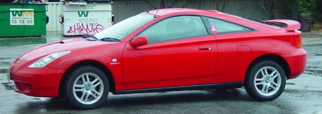
These cars feature a pair of seats in front row and no rear seat. Sometimes a pair of rear seats available. But in most cases there will be only a door per side.
3.3.1.4 Convertible Car

These cars usually referred to as Convertible . They feature a convertible roof top either Soft Top / Hard Top. There are several retractable Hard Top cars. These cars typically does not have large Luggage Space as much as of a Hatchback or a Saloon Car.
3.3.1.5 Estate Car
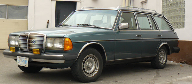
These cars have an additional Pillar than usual cars allowing the roof top to be extended allowing more space for luggage. These also have a additional door placed in back to give access to Extended Space. There are two pairs of seats.
3.3.1.6 Pickup Truck / Vehicle
These cars usually have two doors, some models have 4 door design. In addition these cars feature a Rear Space allowing Large Cargo Space.
3.3.1.7 Van
These type of Vehicle is mainly used to transportation of lighter goods than People, and sometimes used to transport People also.
3.3.2 Heavy Vehicles / Commercial Vehicles
These are type of vehicles typically used in transportation of Goods for commercial purposes. The main types of the Heavy Vehicles are categorised as
- Lorry / Truck
- Trailers
- Semi-Trailers
3.3.2.1 Lorry / Truck
These a medium weight vehicles. These are inbetween Weighs of 4.5 Tonnes to 10 Tonnes when fully loaded. These vehicles mostly have one or two axeles and Rear Powered.
3.3.2.2 Trailers
These are heavy weight vehicles composed of a Cab and a Trailer. The Cab contains Driver Seat and have Heavy Duty Engine.The Cab also features wheels that are Rear Powered. Usually a Cab is 4-6 Meters in Length. The Trailer which is about 10 - 13 Meters in Length attached to Cab via specially designed joints.
3.3.2.3 Semi-Trailers
These are medium or heavy weight vehicles which are attached to a Specially designed Lorry or Truck. These are attached via a dolly.
#Classification of Engines
3.4 By Principles of Working
The principle of working is a important classification of the engine. The engines work differently according to their specifications under these main principles of operation. They are
- Four Stroke Engine
- Two Stroke Engine
- Rotary Engine
3.4.1 Four Stroke Engine
3.4.1.1 Little History of Four Stroke Engines
The four stroke cycle was invented by Nikolaus Otto in 1870s and it is called Otto Cycle in respect to his invention. The invention was not patented properly and it went universal. The Otto Cycle is used in most of the latest automobiles because of its efficiency than other cycles.
Few years later Edward Butler came up with Petrol (Gasoline) Internal Combustion engine. Butler coined many of the terms of the 4 stroke engines. He invented further accessories to assist internal combustion and to increase efficiency. He was the first person to use the Term Petrol. He invented the following items in addition to Petrol Engine.
- Spark Ignition Plug
- Ignition Magneto
- Ignition Coil
- Spray Jet Carburetor
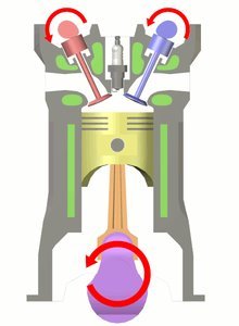
3.4.1.2 Mechanism of a Four Stroke Engine
The four stroke engine completes two rotations per power stroke. Thus resulting in 4 strokes. One Stroke is regarded as the movement of Piston from TDC to BDC or BDC to TDC. The Four strokes can be listed as follows
- Intake Stroke - Piston moves from TDC to BDC
- Compression Stroke - Piston moves from BDC to TDC
- Power Stroke - Piston moves from TDC to BDC
- Exhaust Stroke - Piston moves from BDC to TDC
3.4.1.2.1 Intake Stroke
In this state the inlet valve opens up paving way for fuel air mixure to enter the cylinder. During this course the piston moves from TDC to BDC. This makes enough room for Fuel Air mixure to get into the cylinder.
3.4.1.2.2 Compression Stroke
In this state the inlet valve closes down while the outlet valve remain closed. During this course piston moves upwards from BDC to TDC. This compresses the fuel air misture into the combustion chamber. Thus making the ignition more powerful.
3.4.1.2.3 Power Stroke
In this stroke both valves remain closed.During this course the ignition or spark plug fires causing a spark inside the combustion chamber. It makes the compressed fuel air mixture to ignite with higher amount of power.Due to the ignition of the fuel the piston moves back to BDC from TDC.
3.4.1.2.4 Exhaust Stroke
In this stroke the outlet valve is opened to allow exhaust of the burned fuel air mixture. In this stroke the piston moves back to TDC due the action by the flywheel.During this action there is no power is being generated and the engine completely depends on the flywheel.
3.4.2 Two Stroke Engine
3.4.2.1 Little History of Two Stroke Engine.
By the time of invention of Four Stroke engine concept, there was no two stroke engine concept. The Two stroke engines invented shortly later. The two stroke engines complete the four steps of four stroke engine in two steps. Thus reducing much of the moving parts necessary. These engines do not feature a special lubrication material. The lubricator is mixed with fuel prior to fuelling or by the fuel pump. The ratio of the fuel and oil is 20:1. The oil is usually called 2T Oil.
3.4.2.2 Mechanism of a Two Stroke Engine
The two stroke engines completes one rotation per power stroke thus having a power stroke each time the piston head moves to TDC. The engine has high power outcome than Four Stroke engine due to power per stroke action and it makes the engine more fuel agnostic. The Two strokes are
- Compression and Power Stroke
- Intake and Exhaust Stroke
3.4.2.2.1 Compression and Power Stroke
The fuel is compressed to the combustion chamber by the piston in this stroke. As the piston reaches the TDC, the fuel is fired on the spark ignition concept and the ignited fuel forces the piston to move downwards and enter the next cycle.
3.4.2.2.2 Intake and Exhaust Stroke
As the piston reaches the BDC from TDC after the Power Stroke. The inlet valve and outlet valves are opened at the same time thus making the new fuel flow into the chamber replacing the exhaust gas. In a shortwhile the piston moves up for the next stroke preventing much of new fuel from escaping the combustion chamber.
3.4.2.3 Advantages of the Two Stroke Engine
- The Engine can be fitted to any angle.
- The Engines do not require a maintenance of a lubrication material.
- Produces high power than a Four Stroke engine.
3.4.2.4 Disadvantages of the Two Stroke Engine
- The engine requires high amount of fuel.
- The engine is more prone to friction and heat problems.
- Engine produces high amount of soot than usual.
3.4.3 Rotary Engines
3.4.3.1 Little History of the Rotary Engines.
During World War I & II , these types of Engines were constructed to provide much power than conventional four stroke / two stroke engines. These engines usually had pistons arranged in a circular order, thus connecting to a single crankshaft. These engines were unbalanced at higher speeds due to the heavy moving mass outside of crank case.
The earliest patented design was Atkinson Cycle which is now constructed as a Rotary Engine Cycle with higher efficiency. The patent was granted in 1886 in United States and earlier in European Countries.
In 1929 , Felix Wankel patented his design of a Rotary engine which reduced much of the problems in most of the rotary engines and other reciprocating engines. The working prototype was constructed as of 1955 and the license to produce the engines were sold to Automobile companies around the world. The Wankel engines were highly utilised by Mazda, a Japanese car manufacturer. The development of Wankel engines done by Mazda until 2011.
The Wankel Engines still today remain productive. The engine was vastly improved by Mazda. Due to the higher emission ratio than the Four Stroke engines, the Wankel’s Engine are abandoned in favor of Four-Stroke engines.
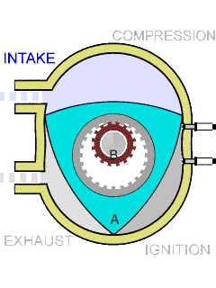
3.4.3.2 Mechanism of a Wankel Engine
The Wankel engine has a different concept than of a Reciprocating Engine. Wankel engines produce a lot of power per rotation of rotar, while cranks produce less amount of power. The Structure of Wankel engines allows to place simple inlets than a complex cams operating to intake and exhaust gas. The typical four strokes of a Four Stroke Engine happens in Wankel engine. The four strokes complete in one rotation.
The Wankel engine always have three simulantaneous actions out of intake,compress, ignite or exhaust happening in Three Chambers.Thus Wankel engine have a rotar with 3 faces, this makes Wankel engine to do 3 powered pushes per rotation.
The Wankel engines typically have apexes in the rotars which seal each chamber. The apex seals are not much durable as they slide along the Engine’s curves.
3.5 By Ignition Mechanism
3.5.1 Spark Ignition
In this mechanism, the fuel is spark ignited and the ignited fuel burns at a quick pace to produce power. This type of engines are mostly Gasoline based and do not carry a special fuel injector to compress the fuel.
3.5.2 Compression Ignition
In this mechanism, the fuel is compression ignited or burned by the high pressure of the combustion chamber. These engines do not require special mechanisms for spark generation, thus reducing parts of engine. This type of engines are mostly Diesel based and do not have a special ignition system in place to ignite the fuel.
3.6 By Cylinder
3.6.1 Single Cylinder Engine
The single cylinder engines are primitively used in Motor-bikes and less powered vehicles. The engines produce lesser amount of power due to the power stroke is 1:4 in any given occasion.
3.6.2 Double Cylinder Engines
The double cylinder engines are mostly used in few vehicles due to its instability of mechanism. These engines produce significant amount of power, but these engines face a great deal of instability due to counter-strokes of each cylinder in a cycle. To avoid this problem, another moving weight balancing part should be used in place. The most notable vehicle using the engine is, TATA Motors’ Nano cars. These engines have a power stroke ratio of 1:2, with a power stroke for a cycle completion of crank.
3.6.3 Triple Cylinder Engines
These engines are used in many vehicles during the 1940s to 1990s. The production of these engines were stopped after creation of stabilised 4 cylinder engines. The engines does not break the stability due to the third cylinder, and had been the most fuel efficient engine of all time.
3.6.4 Four Cylinder Engine
These engines are widely used since 1950s. These engines produce significant amount of energy enough to run a vehicle with heavy weight. The engine achieves a power stroke ratio of 1:1 per stroke in the engine. Thus producing more power than expected.
3.6.5 Six Cylinder Engines
These engines are unusual and mostly employed in sports vehicles to produce a great deal of power. Thus powering the vehicle to high speeds. The engines become more stable as the strokes happen more frequently and the efficiency of the whole output of the engine is awesome.
3.6.6 Eight Cylinder Engines
These engines are also unusual and mostly employed in sports vehicles. These engines are mostly configured in a V-type configuration to save space. Four cylinders per side is configured to save space in the V shape.
3.6.7 Twelve Cylinder Engine
These engines are rare and mostly used in special editions of sports vehicles. These engines produce high amount of power. These engines are usually configured in W mode to save space. This enables engineers to pack 12 cylinders in a space slightly larger than V8 engine. Each side of the engine carries 6 cylinders to a total of 12 cylinders.
3.6.8 Sixteen and Eighteen Cylinder Engines
These engines are ultra rare and no more produced due to need of more space and less efficient in producing great deal of power. These engines were also configured in W configuration. These engines were larger than typical W12 engines.
3.7 By Cooling Mechanism
There are different methods of cooling applied to the engines. In the beginnings the engines were air cooled and the heat produced by the engines was lower enough to be cooled by the air. In the midst time, there was a increase in the heat, and the liquid based cooling system was introduced to resolve the problem. At later times, Volkswagen group redesigned the air-cooled engine into “Volkswagen Beetle”. Current times, the liquid based cooling systems are used mostly in Cars and other big vehicles. Primarily, a special coolant is used as the liquid. Smaller vehicles like Motorbikes tend to use the Air cooling system.
3.7.1 Air Cooled Engines
These engines typically consist of fins along the cover of the engine cylinder to release the heat to the air. The fins are cooled by the air and then the engine is cooled. This cooling mechanism is mostly vulnerable to freezing and harder to work in hot environments.
3.7.2 Liquid Cooled Engines
These engines typically consist of a water line through the engine. The holes in the engine body allows the coolant to enter and leave the engine. The movement of the coolant is controlled by a thermostat with the help of a pressure pump.
3.8 Power of Engine
The power of a engine is usually measured in Horsepower addition to Watt. The method originated in the 19th Century, when Daimler used to compare the power of a Engine driven vehile to a Horse Driven Cart.
One Horse Power roughly equals to about 745 Watt. The horse power is usually denoted as BHP(Breaking Horse Power), It is the maximum power output of the engine.
{pagebreak}#Types of Engines
Throughout the history of the Automobiles Engines played a major role in controlling the speed.There were many experiments regarding the Engines after Renaissance. In the 19th Century historical breakthrough was done by Nikolaus Otto by inventing the four stroke Petrol Engine. There were many improvments to the engine parts since the invention of the Engine.
3.9 History of Engines
3.9.1 Steam Engines
In 18th and 19th Centuries there were inventions of Automobiles that run by Steam Power. Few of the constructions were proved to be successful regarding the efficiency of the system. The cars contructed using the steam engines were slightly bigger than Horse Driven Carts.
3.9.2 Earliest Internal Combustion Engines
The earliest internal combustion engines were built around 1830-1880. Those engines utilised various Technologies.Thus providing different efficiency ratios. These engines mostly used Plant Oils and sometimes Petroleum derived fuels to power the engines. The engines were primarily based with Ignition of the fuel until Rudolph Diesel invented the Diesel Engine which works by burning the fuel in high compress of 50,000 times of atmospheric pressure.
3.9.3 Improvements to Increase the Speed
As the commercial drigging of Fuels began in 1850s , there was a great percentage of inventors using the Petroleum derived fuels. Thus increasing the speed of the vehile by many times. Petroleum fuels consists of high calorie content. They provide high ignition and burning power.
3.9.4 Improvements in Fuel Usage
Until the invention of the Four Stroke Engine by Nikolaus Otto in 1880s the fuel usage of the engines were very high. The Hudson Engine which Hudson invented few years back in time when the Otto’s Engine invented worked with twice the Power of the previous engines with less fuel consumption. In 1880s Nikolaus Otto created Four Stroke engine with high efficiency by mising Air with fuel before ignition inside the Combustion chamber. The engine was not patented properly and the Four-Stroke mechanisms and Reciprocating Action went universal.
##Mechanisms of Engine Parts
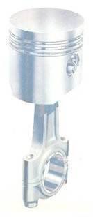
3.9.5 Piston
Piston moves up and down when Engine works.This creates a reciprocating movement. Piston consists of several parts which are used to modulate piston movements and increase efficiency. Piston usually consist of Piston head and Piston rings and other various accessories.Figure MOEP.1 shows the general structure of a piston.
3.9.5.1 Parts of a Piston
- Piston Head
- Piston Rings
- Gudgeon Pin
3.9.5.1.1 Piston Head
The Piston head is a important part which faces the combustion chamber. This is usually made up of elements which can withstand high heat with low malleablity.
3.9.5.1.2 Piston Rings
The Piston Rings wipeout the Oil of crank case and protect the heat gases from entering crank case. Thus preventing the mixture of Oil and Fuel. When piston rings wear off, the oil and fuel mixup in combustion chamber and forming more soot.
3.9.5.1.3 Gudgeon Pin
The Gudgeon Pin connects the Piston with Connecting Rod. The hole is located in the center of the Piston Head.
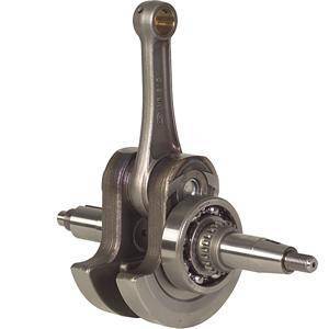
3.9.6 Connecting Rod
The connecting rod connects the piston to crankshaft thus involving in the power transmission to the wheels. The connecting rod moves in a rotating reciprocating motion. The connecting rod can be connected to crankshaft in two ways. Both can be observed in the Figures MOEP.1 and MOEP.2.
3.9.7 Crankshaft
The crankshaft plays a major role in transmitting the power and it connects the connecting rod to crank. Crankshaft involves in a rotating motion. One rotation of crank is called a Crank Angle. One rotation equals 360° of Angle.
3.9.8 Combustion Chamber
This is where the combustion takes place inside the cylinder. the space between the TDC and the spark plug. This is usually have volume of few cubic centimeters. It may be a larger area about 100cm3-2000cm3 in larger engines.The combustion area is small compared to cylinder capacities and it makes the ignition of the fuel to produce maximum power.
The combustion chambers can be further classified by the shape of the chamber.
- Pancake
- Wedge
- Hemisphere 4.
3.9.9 Valve Mechanisms
The valves operate in timing regarding the rotation of the piston. Thus connected to the mechanism by a camshaft and a sprocket chain. Cams located in the Camshaft open and close the valves. When both valves operate , they will be simultaneously open for a small period of time when piston reaches TDC in a Exhaust Stroke. This is called Valve Overlay.
3.9.10 Liners
The Liners are used in Automobile engines which are used for more time than usual to reduce the damage caused to the engine cylinder. These liners separate cylinder walls from touching the moving piston head. There are two types of Liners.
- Dry Liners
- Wet Liners
3.9.10.1 Dry Liners
The Dry Liners can be used in any kind of engines. These liners can fit any type of engine. As the coolant doesn’t have direct contact to the liner, it is less efficient in cooling down the engine. These liners have direct touch with the Cylinder Walls, thus providing great amounts of power to be used on. These Dry Liners are made from high quality Hardened Metal(High Grade Cast Iron) or High Carbon Steel.
The Dry Liners are placed into the Cylinder after heating the cylinder then cooled down to normal temperature. In some engines the Liners are cut perfectly and placed with Little Pressure.
3.9.10.2 Wet Liners
The Wet Liners are used in engines with high heat emissions to reduce the heat of the engine. As the liner have direct contact to the Coolant it is more cooler than dry liners. But the Wet Liners are slightly thicker than dry liners.
3.9.10.2.1 Advantages of Wet Liner
- Very fast cooling system.
- Installation and Uninstallation is easier than Dry Liner.
3.9.10.2.2 Disadvantages of Wet Liner
- Cooling liquid may leak into crankcase although water seals are placed at top and bottom.
- As it does not have touch contact with the Cylinder Wall, it is more weaker than Dry Liner.
3.9.11 Cylinder
TDC means Top Dead Center which is the Top Position, a Piston Head can reach and the BDC means Bottom Dead Center which is a Bottom position which Piston Head can go down inside Engine.
Piston moves from TDC to BDC ,while Crank finishes a Half-Cycle.The image on the left explains it.Whenever a Crank finishes a rotation , Piston moves from TDC to BDC and BDC to TDC. This movement is called Reciprocating Motion, while the Rotation of Crank is called Rotary Motion.The Reciprocating Motion and Rotary Motion happens simulantaneously inside the Engine.
For these actions to happen , Power should be given. When the Heat is given as Power, the Engine is called a Heat Engine. If the Power is generated inside it is Internal Combustion Engine and If the Power is generated outside it is called External Combustion Engine.
In the Internal Combustion Engines Gasoline(Petrol), Diesel are generally used Fuels, whereas Liquid Petroleum Gas is used in some Engines. Inorder to Ignite the fuel, Air is required.Therefore the Fuel is mixed with Air in a Separate Module and the Fuel Air Mixture is ignited inside the Combustion Chamber.After Ignition the Exhaust gas is expelled out from the Combustion chamber by Exhausting equipments.
When a Combustion cycle finishes the Engine should be powered again to return the Piston to the Starting Point as there is no Combustion takes place in the rest of the Cycle. A flywheel attached to the Crankshaft inorder to give back power Generated during Combustion Stroke.Flywheel mostly a three quarter wheel.
#Identifying Parts of Automobiles
There are parts in a Automobile which are necessary for the functions of the vehicle. Each component carries a prominent functionality which they correspond to.
3.10 Chassis of a Automobile
A chassis is usually the part of the vehicle where all of the parts of the vehicle are attached to. The chassis remains a stronger object frame made of hardened metals like High Carbon Steel. These chassis transfer the weight of the whole vehicle to the wheels through the axeles.
3.10.1 Engine / Electrical Motor
The Engine or the Electrical Motor is an important part of a automobile. It produces the power required to move the vehicle. The power throughoutput of the engines are usually measured in Horsepower or Watts, and its exactly termed as “Breaking Horse Power”.
The largest Breaking Horse power produced by a engine is 1200 by a Bugatti Veyron Engine in a W16 Configuration.
3.10.2 Transmission System
The transmission system is important as like as a Engine. The transmission system creates a connection to the engine and the wheels through the differential and propellar shaft. The transmission system’s final throughoutput is known as “Final Drive” and its delivered to the differential via Propellar shaft. The differential then distributes the power to the wheels in a asynchronous way(non-blocking).
3.10.3 Lubrication System
The lubrication system is essential in a Automobile to reduce friction between moving parts. Without a proper lubrication in place the engine would fetch into many ceases within a short time. The lubrication keeps the parts move smoothly by forming a thin layer around most of the moving parts and making them slip without much friction.
3.10.4 Cooling System
The cooling system is critically important to any heat engine to keep it cooled down. Otherwise the engine would go beyond the scales of permitted temperatures and break off. The cooling system consists of various parts to determine the temperature of the engine and keep it cooled down. The cooling system usually uses a special coolant which is resistant to freezing in low temperatures and with different viscosity levels.
3.10.5 Ignition System
The Ignition system is another important part of a engine. Without a ignition system in place, the engine cannot fire the fuel for burning in the correct order. Thus making the engine unusable for any purpose. The Ignition system fires the fuel at the right time according to the position of the piston and the speed of the piston. There are few methods used to determine the speed of the Piston and the position of the piston.
- Centrifugal Advance Mechanism
- Vacuum Advance Mechanism
- Computer Controlled Ignition
3.10.6 Suspension System
The suspension system is an essential part of user experience in a automobile. A Suspension system is required to keep the engine and passengers safe from the vibrations of the wheels and the engine.
3.10.7 Starting System
The starting system is also a necessary part of a automobile. It starts the engine from off state. The starting system checks various elements of the engine before kicking off the start process. It ensures that the engine starts in a safe procedure.
3.10.8 Braking System
The braking system of a automobile is very much important as a engine. The braking system makes the vehicle slowed down and stopped by applying brakes at various wheels. The braking system keeps the automobile stopped at certain circumstances. There are two types of braking components.
- Parking Brake
- Driving Brake
There are different types of braking based on the technology used in braking.
- Air based Braking System
- Liquid based Braking System
4. Starting System
The starting system is necessary in a automobile to start the engine. In Earlier days, the engine was started by hand using a crank. The starting system accompanies the Main Engine. There are several types of Starting Systems.
5. Ignition System
The Ignition System of a Engine is a important part in the work of the engine. without the ignition system the engine cannot work. There will be no ignition. Ignition system consists of several parts which make a complete workout. Those parts are
- Switch
- Battery
- Ignition Coil
- Spark Plug
- Contact Breaker
5.1 Parts
5.1.1 Switch
This acts in turning on and off the whole ignition system. Without a switch in place, a Ignition system cannot be controlled as per expectations.
5.1.2 Battery
The battery powers the ignition system for a cold start. The battery provides the base voltage of 12V which is later converted to high voltages and used in igniting fuel.
5.1.3 Ignition Coil
The ignition coil converts the power from battery to high voltage. The ignition coil consists of two coils namely, Primary Coil and Secondary Coil. The converted voltage ranges from 20,000V to 40,000V.
5.1.4 Spark Plug
The spark plug fires the fuel inside the combustion chamber. The spark gap is set to be 0.8mm to 1.8mm depending on the produced voltage. The electrode openings are made of Nickel to sustain high temperatures and provide a resistant to preheat the fuel.
5.1.5 Contact Breaker
A Contact breaker is placed in between the distributor and the secondary coil to terminate the power according to a timing. without a contact breaker in place, the secondary coil will not produce any power.
5.2 Operation
A switch is placed in action to stop and start the engine when required. Whenever the switch is turned on, it makes magnetic flux in the Primary Coil of the Ignition Coil. It also creates magnetic flux in the secondary coil where as the wheel fixed on the circuit breaker makes a connection. The connection is breaked when the piston reaches TDC during a compression stroke. Thus making the fuel ignite through the spark on the Spark Plug’s ends. The operation of the Ignition Coil is similar to the transformer.
5.3 Ignition Timing
5.3.1 Centrifugal Advance Mechanism
This mechanism involves use of Mechanical components to function. The distributor is powered by the power of the engine and the distributer contains two discs attached to each other. One disc is carved for allowing space of a movable part attached to the other disc. The flyweight attached in the other disc forces the second disc to move ahead of the cycle while both discs are spinning at a high speed. Thus reducing the time taken to fire the sequence.
The advancement of the second disc varies according to the speed of the engine.
5.3.2 Vacuum Advance Mechanism
This mechanism works on the principle of Engine load. When the engine receives a heavy load, the timing shortens accordingly. It produces a high fuel efficiency rate and increases engine life. The advancement in the vacuum advance mechanisms allow greater savings.
5.3.3 Computer-controlled Ignition
Newer engines typically use computerized ignition systems. The computer has a timing map (lookup table) with spark advance values for all combinations of engine speed and engine load. The computer will send a signal to the ignition coil at the indicated time in the timing map in order to fire the spark plug. Most computers from original equipment manufacturers (OEM) cannot be modified so changing the timing advance curve is not possible. Overall timing changes are still possible, depending on the engine design. Aftermarket engine control units allow the tuner to make changes to the timing map. This allows the timing to be advanced or retarded based on various engine applications.
#Transmission System
6. Fueling System
A Proper fueling system is required for proper functionality of a Automobile. If a Automobile has malfunctioning Fueling System, the automobile may use more fuel or less fuel efficient and may produce harmful effects to the whole Automobile. Thus maintaining a fueling system is important in the life cycle of the Automobile.
The fueling system used for Petrol(Gasoline) and Diesel are completely different as both engines work on different cycles and principle. The Gasoline engine works on Otto cycle while the Diesel engine works on Diesel Cycle.
6.1 Petrol(Gasoline) Fueling System
The Petrol engine utilizes Otto Cycle as said above. The Otto cycle ignites the fuel instead of burning the fuel. The ignition causes movement of the piston and produces power. This is completely different from the Diesel Cycle. In the Otto Cycle , Fuel is mixed with air and then sent into the combustion chamber. Thus making the fuel more ignitable.
6.2 Diesel Fueling System
This system also utilises a cycle similar to Otto Cycle. It is called the Diesel Cycle. In Diesel Cycle fuel is burned by compression instead of ignition. The fuel is injected into the Combustion chamber in high pressure, about 60,000 times of Atmospheric Pressure. As the fuel is injected while the piston is moving up, the fuel gets high compression. Thus making the fuel burn and push back the Piston.
6.2.1 Injectors
The injectors in a Diesel engine is very much important part than any other part of the Diesel Engine, thus anything happening to the injectors will directly affect the engine. The injectors are usually controlled by Electronic Control Module(ECM) or Electronic Control Unit(ECU). The injector is initially supplied with a battery voltage via a relay, in which the earth circuit is controlled by ECM/ECU. When the circuit is completed by the ECU a solenoid operates, the injector valve opens, fuel is then able to be sprayed into the inlet manifold. The valve moves roughly 1.5-10 milliseconds. This is known an injector duration or opening time. The ECU will make amendments to the duration depending on engine temperature, loading air temperature and battery voltage
6.2.1.1 Injector Types
6.2.1.2 Common Rail System
6.2.1.3 Jerk Pump System
#Cooling System
6.3 Pressurized Cooling System
{pagebreak}#Lubrication System
6.4 Functions of Lubrication System
The main functions of the Lubrication system are,
- Cooling Down Engine Parts
- Cleaning engine from broken pieces from friction between cylinder and piston.
- Keeping the piston rings and cylinder wall enclosed and keeping it air tight.
- Reducing Vibration between bearings and engine parts
6.5 Types of Lubrication System
There are several types of Lubrication systems. Out of them, these are the major 3 categories.
- Petroil Lubrication System
- Splash Lubrication System
- Pressure Feed Lubrication System
6.5.1 Petroil Lubrication System
Petroil Lubrication system is used in 2 stroke petrol engines. In these oil pump and filter is not used. When its fuelled, 3-6 % of 2T oil is added to the fuel. When engine operates, the fuel air mixture is taken in and the oil mixed in the fuel lubricates the engine parts such as Bearings, Piston rings, Cylinder walls, Piston Pin/ Gudgeon Pin.
6.5.2 Splash Lubrication System
This is used mainly in small 4 stroke engines. On the big end of connecting rod, brearing cap, a rod dipper is attached. Due to the rotational movement, they splash the oil into the engine parts from the oil sunk.
6.5.3 Pressure Feed Lubrication System
This is used mainly in large 4 stroke engines. In this engines, a oil pump and a oil filter is attached. The oil pump forces the oil into the oil filter and after filtering of the oil, the oil travels through the galleries designated to be reached by the oil. Furthermore, it enters sprayers located below pistons. As a result of this lubrication mechanism, a Thin layer forms in between the Cylinder and the piston head, thus filling the space in between them.
Types of Oil Pumps used in this system are
- Gear Pump
- Rotor Pump
- Cresent Pump
6.6 Features / Properties of Lubricant
- High Viscous Point - determines the flowing rate of oil through surfaces and oil films.
- removing waste materials or rust resistance
- viscosity index - the change of viscosity according the heat change in the engine. it is ranged from the 0 to 100, the higher means lesser co-efficeint of change.
- SAE 30W
- SAE 5W - 30 (High Cost, multi-viscosity oil)
ELECTRICAL ENGINEERING
7. Basic Circuit Elements
There are several types of basic circuit elements used to construct the electrical circuits. The following are the important basic circuit elements.
- Resistor
- Capacitor
- Transistor
7.1 Resistor
The resistors are used in electronic circuits to reduce the Voltage and Current flow in a certain section. Resistors are based on the Ohm’s Law which specifies the Current passed through a resistence is directly proportional to Voltage when Temperature and Pressure are at constant values.
7.1.1 Color Codes of Resistors
| Color | Value | Value | Multiplier | Tolerance Level | Temperature Co-efficient |
|---|---|---|---|---|---|
| Black | 0 | 0 | 1 | Not Used | Not Used |
| Brown | 1 | 1 | 10 | +1% | 100 |
| Red | 2 | 2 | 100 | +2% | 50 |
| Orange | 3 | 3 | 1000 | Not Used | 15 |
| Yellow | 4 | 4 | 10000 | Not Used | 25 |
| Green | 5 | 5 | 100000 | Not Used | 0.5 |
| Blue | 6 | 6 | 1000000 | Not Used | 0.25 |
| Violet | 7 | 7 | 10000000 | Not Used | 0.1 |
| Grey | 8 | 8 | 100000000 | Not Used | Not Used |
| White | 9 | 9 | 1000000000 | Not Used | Not Used |
| Gold | 0.1 | 0.1 | 10000000000 | +5% | Not Used |
| Silver | 0.01 | 0.01 | 100000000000 | +10% | Not Used |
7.2 Capacitor
The capacitors can store some current for a small time. It works by using a Dielectric Region, which is actually a insulator.
7.3 Transistor
The first point contact transistor was invented in 1947 by William Shockly, Walter Brattain, John Bardeen. It was a major breakthrough in the Field of Electronical Engineering. Transistor reduced much of the workload caused by using Vaccum Tubes.
8. Electricity and Current.
8.1 Relationship between Voltage,Current and Resistance
The Voltage,Current and Resistance are directly associated to each other. The Ohm’s Law defines these associations.
BUILDING AND CONSTRUCTION TECHNOLOGY
9. Parts of a Building Plan
The Construction plan defines the construction materials required to build the respective building.The construction plan consists of 1. Ground Plan 2. Sectional Elevation 3. Front Elevation 4. Side Elevation 5. Door,Window details 6. Floor Plan 7. Foundation Setup
9.1 Ground Plan
The Parts below roof level of a building is called the ground plan. the marking of the floor is for the Door and Windows . By this the width of the wall and the position of the room and internal measurements of buildings and doors and windows and curves , Door Steps are shown.
Generally when drawing the ground plan , Metric Value are used on a 1:1000 scale. Anyhow in some special occasions the scale may change.
10. Cement
Usually many types of cements are produced. They are used in various instances for which they were developed. For General construction works Ordinary Portland Cement is used.
10.1 History of Cement
“Cement” originated from the meaning of mixing small miniature particles into water and producing stronger bonding. It was named by Joseph Aspdin, a British Engineer.
The function of a Hydrated Cement is alike the process stated. Cement was first used in Egypt and thereafter used in Greek and Babylonia. Romans used Volcanic Dust with Limestone to produce cement.
As of 1871, Cement had been commercially produced in United States of America.Today most of the cement produced is Ordinary Portland Cement.
10.2 Types of Cement
Generally many types of cement are available in market. They are produced for a certain purposes. Mostly Produced Cement Types are
1.Ordinary Portland Cement 2.Rapid Hardening Cement 3.Quick Setting Cement 4.Water Proof Cement 5.High Alumina Cement 6.Sulphate Resistance Cement 7.Masonry Cement 8.White Cement 9.Coloring Cement 10.Low Head Portland Cement 11.Super Sulphate Cement
10.2.1 Ordinary Portland Cement (OPC) - SLS 107
- High Market Availability
- Low Cost
- Usable on ordinary situation for all works Eg:- Concrete, Precast
10.2.2 Rapid Hardening Cement (RHC)
- Produced as like as OPC but the mixture hardens quicker than OPC due to a catalyst.
- OPC needs 28 days to strengthen
- RHC needs 4 days to strengthen
- Cement mixture is produced by adding 2% of CaCl
- The Settling time of this Cement remains same as OPC. This can be used for quick construction works , weight loading works.
- As quickly hardens , the shuttering work can be removed quickly.
10.2.3 Quick Setting Cement
- The Gypsum is not added to this type of Cement Milling.
- Small amount of Aluminum Sulphate - 2% to 4% is added to the mixture while milling.
- Because of these reasons the cement quickly settles down.
- Time Taken to Settle Down - 5 Minutes to 10 Minutes
- This type of Cement is used in locations where more moist is found and helps to quickly settles down.
10.2.4 Water Proof Cement
- In Cement production 2% of Calcium and Aluminum are added to produce this exact type of cements.
- This Cement is typically used in structures which are in subsequent exposure to Water/Moisture.
- The Cement is used 2%-5% in Global Cement usage calculations.
10.2.5 High Alumina Cement
- This cement constitutes of 35% of Calcium Oxide and 25% to 55% of Aluminum Oxide and 5% to 15% Ferric Oxide and 5% to 10% of Silica.
- This cement can sustain its strength up to 1300° Celcius.
- This cement is used in construction of Kilns and High Heat Furnaces.
- This cement can also sustain Acidic and Basic Situations.
10.2.6 Sulphate Resistance Cement
- This type of cement constitutes of
- Lime 64%
- Silica 24%
- Alumina 4%
- Ferric Oxide 4%
- Unlike Portland Cement, this type of cement gains 75% of strength in 3 days and 85% in 28 days. This type of cement resists Sulphate Reactions and Protect Buildings.
- This Cement is used in North America where high sulphate content is found in some soils.
- Drainage and Sewage drains are plastered using this cement to prevent corrosion from chemical substances.
10.2.7 Masonry Cement
- This type of cement is produced by adding more calcium to the clinker.
- This can be more softer than the OPC and easier to work with and can produce more smoother surface.
- This cement has high softening factor, high workability and load reduction.
- As this cement produces softer surfaces , this is helpful in finishing works and reduce further costs in softening.
10.2.8 White Cement
- This type of cement is produced by using the Porcelain(Chinese clay) instead of normal clay.
- Used for decorative works
- The whiteness of the cement has been obtained by addition of Calcium Hydroxide and Ferric Oxide.
- This cement has same strength of OPC, but whiter than OPC.
10.2.9 Color Cement
- This is produced by mixing various colors to OPC. (10% of Color)
- Ferric Oxide
- Red
- Yellow
- Brown
- Manganese Oxide
- Black
- Brown
- Cobalt
- Blue
- Chromium Oxide
- Green
10.2.10 Low Heat Portland Cement
- This type of cement is used in massive construction works like as Dams , Retainer Walls, Bridges.
- This cement produces less heat than Ordinary Portland Cement because of this, hair cracks are prevented from forming in Buildings.
10.2.11 Super Sulphate Cement
- This gives much protection against corrosion.
- When using this cement, up to the curing period, the surface should be maintained wet and curved.
- This cement cannot be stored in high humidity areas.
10.3 Cement Production
10.3.1 Raw Materials
- Calcium Carbonate - 78%
- Purification Factor - 75%
- Available in Sri Lanka @
- Kankesanturai
- Puttalam - Single Layered
- Coral Limestone (Not used as it threatens sea life forms.)
- Clay - 20%
- Consists of
- Silica
- Alumina
- Iron Oxide
- Available in Sri Lanka @
- Murungan , Mannar
- If the Iron Oxide lacks required level, Limonite is added.
10.3.2 Production
Generally cement production consist of 4 steps.
1.Identifying and gaining Raw Materials(Quarrying) 2.Preparation of Raw Materials 3.Clinkering 4.Cement Milling/Rolling
10.3.2.1 Quarrying
Limestone, Clay are obtained from various places and they are stored in separate silos.
10.3.2.2 Preparation State
- Here lime is crushed into small stones and stored.
- Clay is purified of vegetation wastes and chemical wastes and stored.
10.3.2.3 Clinkering
- This step is important in portland cement production.
- Clinkering is done is 6ft Wide, 132 feet long ,15˙ horizontally tilted continous rolling machine.
- The machine’s inner chamber is heated using pressurized gas from furnace fuel or coal.
- It is heated to a maximum of 1400˙ C to 1600˙ C.
- Raw materials are properly mixed and feeded into the machine. These raw materials melt in high temperature and gain several changes. These changed raw materials are cooled in cooling section.
- The clinker produced has the color of grey and are very hard globules.
10.3.2.4 Cement Milling
- Here clinker is mxed with 3% to 5% of Gypsum (CaSO[4] . 2H[2]O) in the Ball mill
- 60 mm diameter iron balls grind the clinker with gypsum.
- Thereafter 30 mm steel balls finely grind the crushed mixture.
- The cement produced is stored in long high raised vacuum silos.
- After that they are packaged in 50Kg bags or delivered in mass amounts
10.3.3 Physical Features of Cement
10.3.3.1 Finess
Small particles are the best for the tidyness of the cement. This applies British standard (BS-12(1991)) to OPC and 325Kgm-2 Finess enables to work easily but cost more on production of it. The water absorption late is low. More finess increases chances for hair cracks
10.3.3.2 Hydration
The chemical constituents or componds react with water is called hydration of cement. Because of this reaction, cement forms a strong bonding with sand and stone. By hydration, heat is produced. This does not affect small scale works, through adversely affects in large or very large scale works. Concrete works done in cold season take advantage of heat but in hot season large scale construction works produces thermal cracks in concrete.
10.3.3.3 Soundness
No change in the volume after strengthening of cement is called soundness of cememnt
If cement contains calcium oxide or magnesium oxide in unacceptable amounts, its called the unsoundness of the cement
10.3.3.4 Setting time and Strengthening
This is connected to the hydration of cement and the start of the reaction of cement with water is the initial setting time.
- OPC - 30 Mins
- QSC - 5 Mins
The setting time depends on following factors
- Composition of Cement
- Finess of Cement
- Hydration rate of Cement
- Environment Temperature
10.3.3.5 Strength
The strengthening factor of cememnt is important. The strengthness of cement depnds on
- Physical and Chemical features of Cement
- Curing method
- Water and Cement ratio
11. Lime
Lime is an ancient construction material used in Sri Lanka. This is mostly used in Anuradhapura and Polonnoruwa. The lime paste is used in Sigiriya.
These days cement has replaced the Lime in most cases but in some instances to obtain better finish of building in the inside, the Lime is used.
11.1 Raw Materials of Lime
The raw materials for lime are derieved from the following
- Limestones
- Seashells
- Coral Reefs
- Dolamite
Raw lime also contains contaminents such as MgCO[3], Al[2]O[3],SiO[2]. The standard for Lime is, SLS:552 (1982).
1 CaCO[3]         -->    CaO + CO[2]
2 CaMg(CO[3])[2]  --> CaCO[3]+ MgO + CO[2]
The quicklime is obtained by heating pure limestones, seashells to 900° C. Pouring/Spraying water on the quicklime produces Hydrated Lime Ca(OH)2 or Slake Lime.
11.1.1 Hydration of Lime
During this procedure, Calcium Oxide is exposed to water. By doing this,
- Cracks form
- Engorges to large space
- Gains granularity of powder
- Subsequent levels of heat and steam release
CaO + H2O —> Ca(OH)2
This operation is normally handled in Kilns straight after obtaining Quick Lime. The unburnt or overburnt lime must be removed before this procedure.
12. History of Building and Construction Technology
The building construction technology has existed since evolution of human civilization. It had grown throughout the times and today it had reached miserable status. In this way, the people of ancient civilizations has used excellent technologies to construct buildings. That has been proved by 1. Egytian Pyraminds 2. Mohanjadaro Harappa Buildings 3. Roman Buildings - Colosseum
In Early times human dwellings have consisted of caves. Later on humans had created various architectural achievements.
13. Materials for Construction of a Building
There are several materials required to construct a building rather than construction materials. They can be either legal documents or drafts about the building.
13.1 Classification of Construction materials
| Natural | Artificial | Solid | Liquid | Binding | Protection |
|---|---|---|---|---|---|
| Lime | Cement | Cement | Water | Cement | Concrete Stone |
| Sand | Concrete Stone | Concrete Stone | Paint | Lime | Brick |
| Rubble | Brick | Brick | Sand | Cement Block | |
| Water | Cement Block | Cement Block | Water | Bricks Hold | |
| Bricks Hold | Bricks Hold | Glazed | |||
| Glazed | Glazed | Steel Rods | |||
| Steel Rods | Steel Rods | Metal Plates | |||
| Metal Plates | Metal Plates | Copper Pipes | |||
| Copper Pipes | Copper Pipes | Galvanized Pipes | |||
| Galvanized Pipes | Galvanized Pipes | PVC Pipes | |||
| PVC Pipes | PVC Pipes | Paint | |||
| Paint | Lime | ||||
| Sand | |||||
| Rubble | |||||
When using the above materials , general information about features of them are required. * General Physical Features * Density/Thickness * Usability * Cost * Malleability * Thermal Factors * Ignition Rate * Boiling Point * Expansion Ratio * Thermal Capacity * Heat Transfer Rate *Chemical Features * Irritation Resistance * Surface Pull Rate * Water Absorption Rate
14. Mortar Joints of Bricks
14.1 Importance of Mortar Joints
14.2 Features of General Brick Contruction
15. Concrete Bricks and Closers
15.1 Closers
15.2 Concrete Bricks
16. Usage of Concrete in Constructions
16.1 Raw materials of Concrete Mixture
16.2 Mixtures of Concrete based on Constructions.
16.3 Concrete Reinforcement
MATERIALS AND THEIR CHARACTERISTICS
17. Materials
18. Using Various hand tools
19. Moulding
19.1 Simple Moulding Methods
19.2 Complex Moulding Methods
20. Cutting Metals and CNC Machines
Annex
Model Paper 1
Part I
- What is the equation for Ohm’s Law?
- V=I/R
- V=IR
- VI=R
- VR=I
- The color codes of 39Ω ±5% Resistor in proper order?
- Red,Gray,Brown,Gold
- Orange,White,Black,Gold
- Yellow,Grey,Brown,Gold
- Yellow,Grey,Black,Gold
- The find the proper matching value of Brown,Violet,Yellow,Gold in Resistor Color Codes
- 170Ω
- 1.7MΩ
- 17kΩ
- 170kΩ
- The current of a circuit when there is 10Ω resistance and 250 Volts.
- 230A
- 23A
- 10A
- 40A
- The resistance of two parallel 800Ω resistors?
- 1.6kΩ
- 400Ω
- 800Ω
- 16kΩ
GLOSSARY
TDC - Top Dead Center BDC - Bottom Dead Center