3. MDG Structure
A MDG file is simply a container for several XML files. Most of them being UML profiles. It is possible to create a MDG with a text (or XML) editor and sometimes you really need to do that3. But now we will start the EA-way. And that is by first creating a profile.
3.1 A Profile
A profile is what contains the elements you define for your domain. A profile as such is meant to keep elements. There are profiles for diagrams, toolboxes and other things as well. In those cases the profile will be attributed with the objective.
Since this chapter is named “A Profile” and not “The Profile” you can guess that there may be multiple profiles. However, a single profile will do in most cases. You would use multiple profiles if you can identify multiple sub-domains which need different treatment. Using multiple profiles is not much more difficult than using a single one. So we start with the profile for our example domain.
Copy
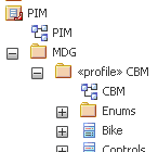
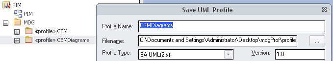
The following is one way to achieve the desired results. But for me it’s the best way. It starts with creating a deep copy of the domain model. Just Ctrl-C with the focus on the Domain Model in the project browser4. Go to the PIM view, create a folder MDG, select that and press Ctrl-V. This will create a deep copy of the domain model. Now edit the properties of the copied Domain Model. You should rename it to some acronym for the domain since this name will be needed to reference elements which you need to type manually later. In my example it is CBM for Custom Bike Manufacturer. Further you must assign the stereotype <<profile>>. Don’t forget to rename the contained diagram as well (with no need to add a stereotype). It should look like this:
Now if you open the diagram and press the space bar you will see that the toolbar shows no longer those of a class diagram but that for a profile.
Cut
The copied domain model still contains all business objects. But often we do not need to model all of them. E.g. the Tool is just an abstract classification to have tools inherit the vendor. So it is not an element you would later include in your modeling process.
Cutting away those elements will save you some work ahead. Still, if you find a need for those deleted elements later you can create a new copy from the domain model. Instead of cutting elements away you can simply stow them in a package named Not used or Future use.
Edit
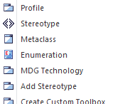
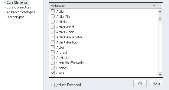
Next create a folder metaclasses inside the profile folder. From the new toolbar choose Metaclass and inside select Class:
This creates a stereotyped class. In the project view drag it into the metaclasses folder so it does not clutter the domain objects on top level.
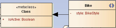
The following steps might be tedious. Start with one of the classes and add a stereotype <<stereotype>> manually (without typing the guillemets!). This will add a stereotype icon to the class and the quick-linker will offer an Extend relation. Just create that as link to the Class metaclass:
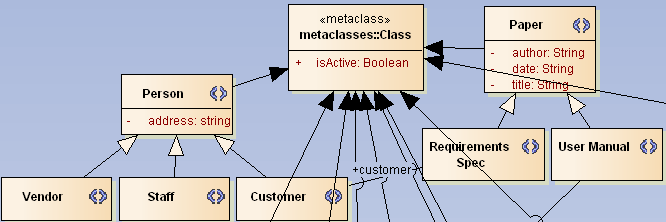
Assuming that all of the domain objects will result in classes continue changing their stereotype and linking them to Class. So you end up in some garbled diagram like this
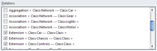
Finally remove the metaclass from the diagram with Delete (not Ctrl-Del since that will delete the element completely from the model). You can show the relations in a new diagram named Class inside the metaclasses package. Drag Class onto that diagram and from the context choose Insert Related Elements. Now you need to hide all relations except the Extend. This is best done opening Diagram/Visible Relations and uncheck those to hide:
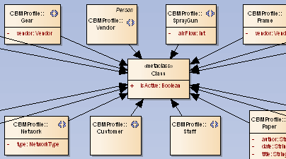
A simple auto-layout (and optional manual work) will then result in something like this:
A First Test
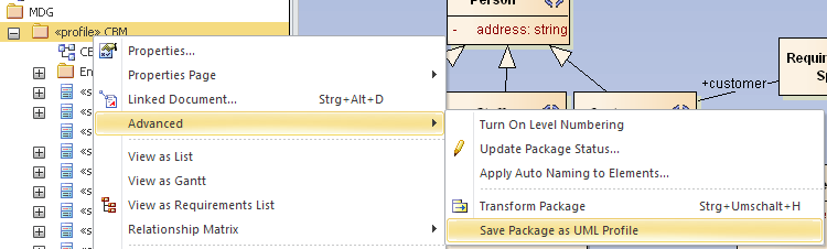
At this stage we are ready for a quick test of the new profile. Therefore the profile needs to be exported to a XML file. Select the profile package and from the context menu Advanced/Save Package to UML Profile. Choose an arbitrary file location.
The next step is to import the profile so it can be used. Open View/Resources, from the context of UML Profiles choose Import Profile
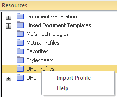
and select the previously exported XML file. Now you can see all the elements that had been defined.
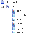
If you have not done so create a view Sandbox with a class diagram and open the latter. Then drag one of the elements from the UML Profiles onto the diagram. It will create a new class stereotyped with the name of the chosen element. Additionally the tagged values (TV) are populated with the attributes defined in the profile:
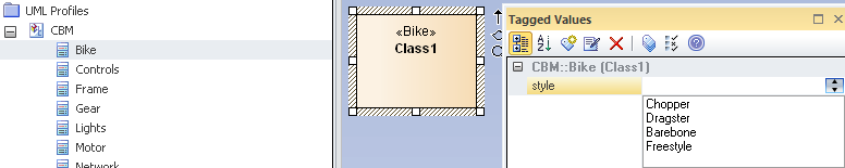
In the above example the Bike comes with the style as TV with a drop down containing the bikeStyle enumeration values. So far, so nice.
Now we try the same with the Tool:
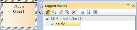
The TV size resulted in a simple input field which is also nice. But the vendor shows up as empty group. Here we ran in one of the bugged features in EA. The stereotype Vendor has been generalized from Person and thus should have an address property. But EA silently ignores them here. One needs to copy inherited attributes from the general class. YAEAB.
You can go on verifying that all profile elements work as expected. Then you can delete the profile from the Resources (use the context menu). Once deleted the TVs in groups are no longer grouped/available but that’s ok since this was just a test and the elements in the sandbox can be thrown away as well. Note that the stereotypes from Project/Settings/UML Types will also be gone.
Extending/Completing the Profile
At this stage you will get a good feeling for what your profile is good for. The more complete your profile is, the less you have to fight with fixing an incomplete profile later. However, in order to get an overview of the whole picture we will carry on with the other two most important parts of a MDG: diagrams and toolboxes. We will care about details of a profile in chapter Advanced MDG Techniques.
3.2 Custom Diagram
While the profile holds the Lego stones for your model the custom diagrams are like frames for the presentation. There is no special rule as to which diagram will be needed. But usually you connect it with a certain design process. You probably have some sort of element sets that belong to each other. In our example domain you will eventually have different sets for technicians, designers or sales persons. As you can see they are all actors we defined previously and so you can create actor-centric diagrams. Often processes and actors are related so actor-centric will also mean process-centric.
You should already have in mind that the limitation of elements per diagram will be controlled via toolboxes (which will be detailed in the next chapter). Another use for custom diagrams is to replace the standard UML diagram with a set of a reduced number of elements. So you would have your own class diagram but with your own reduced and/or augmented set of elements.
Let’s assume that we need two extra diagrams for the commission and the design process. Start by creating a new package named CBMDiagrams inside PIM/MDG, assigning it a stereotype <<profile>> and creating a class diagram inside. Having that diagram open hit the space bar and create two Stereotypes Commission and Design
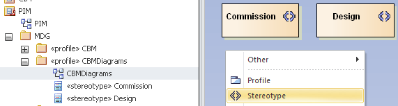
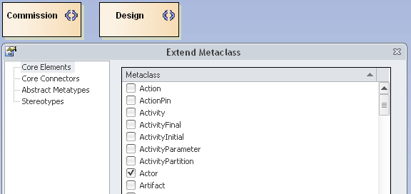
that will represent our custom diagrams. Next you need to make them extend diagram metaclasses. Create a new metaclass for Actor:
Now you need to rename the new metaclass to something like Diagram_<base> where <base> must match one of the basic UML diagram types. According to the EA help these are
- Activity
- Analysis
- Collaboration
- Component
- CompositeStructure
- Custom
- Deployment
- InteractionOverview
- Logical (for Class diagrams)
- Object
- Package
- Sequence
- Statechart
- Timing
- Use Case (note the space between the two words)
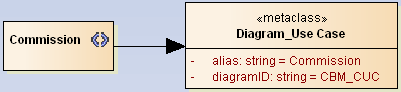
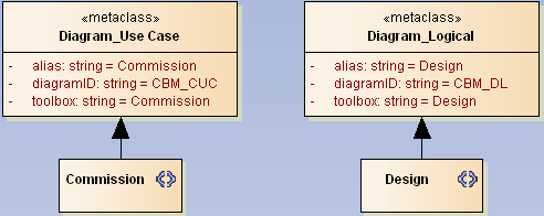
So we name the first one Diagram_Use Case and add two attributes. The first is alias5 with a default value of Commission. This value will appear in the diagram creation dialog later. The second is diagramID which needs a unique string. I assign the company initials followed by an underline and an acronym of three chars or so which describes the diagram. Here it will be CBM_CUC (for Commission Use Case). You are free to use any other scheme you like, though.
Now an Extends relation needs to be drawn from Commission:
Repeat that with Diagram_Logical, Design and CBM_DL (for Design Logical) so we are ready for the next test.
Prepare for a quick test
Testing the newly created diagrams is not that easy as testing the above profile. We need to create a basic MDG right now. Before we can create it there needs to be some folder structure on disk. Locate some place where you want to create that folder so you can find it back easily. I named it mdgProf but you are free to find another suitable name. A number of files will go into that folder. I also place the final MDG inside. Later you might find another location for it, be it a shared folder or some place on a version control system. But I usually stow it here for testing and eventually copy the result when needed to the final location.
The folder will later hold a so-called MTS file which EA uses to store file locations needed to create the MDG. I create three folders named profiles, diagrams and toolboxes inside which are used to store the exported profiles.
As a first step export the profile to the profiles folder. Since in our example domain there is just one single profile it is named CBM.xml. In case of multiple sub-domains the single profiles will be named according to them.
Now the diagrams profile needs to be exported similarly. From the CBMDiagrams folder choose Advanced/Save Package as UML Profile and store it as CBM.xml in the diagrams folder.
The toolboxes stays untouched for now and we can start creating the MDG. Select Tools/Generate MDG... from the menu and click Next. Since this is the first time we choose to create a new MTS file and click Next.
The following dialog requests a couple of information:
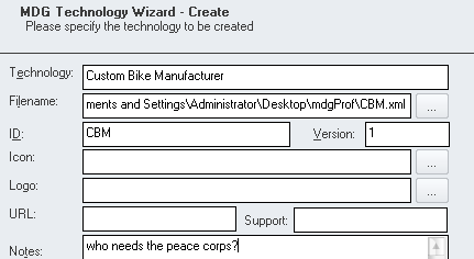
Technology might simply be named after the company. If you have the need for multiple MDGs in a company you will likely be experienced enough to find meaningful names.
Filename will be that of the created MDG. As said I simply put that into the mdgProf folder named CBM.xml.
ID can simply be the company acronym (or the name of the MDG repository root node). And Version is some n.m scheme. Be warned that changing that number might become necessary and will easily bring you into trouble. We will be talking about that in chapter Versioning Profiles. For now just put a 1 into it.
All other fields except Notes can be left blank for now. The Notes will appear in the MDG activation dialog and is meant as a short description. So put in some meaningful text here and click Next.
This will ask you for the location where to save the MTS file. As said, just place it at top level inside the mdgProf folder.
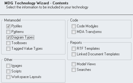
Next we need to tell which profiles we want to add to the MDG. Since we have profiles and diagrams these options need to be ticked. And Next.
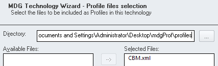
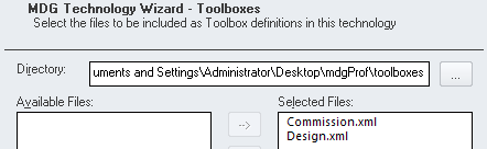
For each of the ticked options EA will ask for the related XML files. So in the first dialog locate the mdgProf/profiles/CBM.xml and in the following mdgProf/diagrams/CBM.xml. Then move them from Available to Selected Files.
From here click Next until the dialog is done. The MDG is now stored to where you told (in above case it’s located at mdgProf/CBM.xml. To utilize this MDG we can stick to the resources view (see First Test) but rather than UML Profiles we would use MDG Technologies to where we import the new MDG.
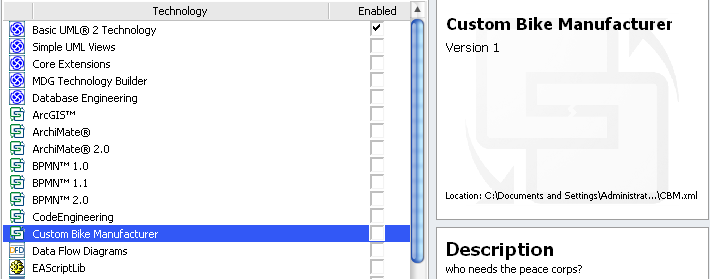
When done you should see the MDG in the list of available MDGs where you just need to enable it.
A quick test (finally)
Select the Sandbox view and click the New Diagram icon. Now you should see the technology listed containing the two diagram types we had defined.
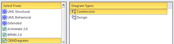
As you can notice the visible diagram names are those from the alias attributes defined above. Also you can see that the Commission diagram is an use case diagram and the Design is a class diagram. Go ahead and create both diagram types in the Sandbox folder. You will see that the toolboxes are as one would expect for either class or use case diagrams.
Now export one of those diagram via Diagram/Save Image to File... and you will see (for the Commission diagram)
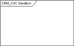
The diagramID we had defined as attribute is prefixed to the name of the diagram in the frame.
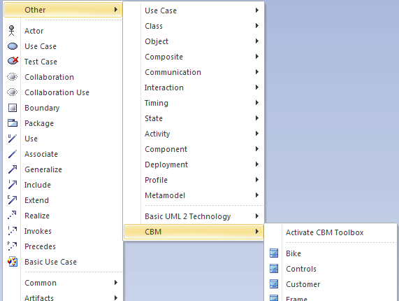
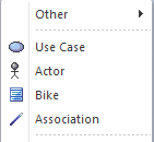
And where are the elements from the profile? Well, currently they are a bit hidden. You need to navigate through the Other sub-menu from the toolbar to find them. Here you might activate the profile so it can be found more easily.
Remember that until now we have not connected the diagram with any toolbar. But we are close to that step.
Updates
At this stage the testing of the MDG will become a bit more tricky – simply because a number of different files are involved which need to be saved separately. Still these are just two but when you save any of the profiles you will see this:
In order to reload a newly generated MDG you can simply load it again via the resources view. Any previously loaded MDG will silently be replaced by the new one as long as it has the same ID.
3.3 Toolboxes
Connecting custom diagrams with toolboxes will unleash most of the power which MDGs offer. Of course there’s even more to come, but having a grip on this will give you the most power for the least effort. So lets get it.
Like for the diagrams we first create a CBMtoolboxes package. But then we need to create a separate diagram for each toolbox and name that diagram accordingly. What we want to achieve is that each of the custom diagrams has a related toolset with just those elements which are relevant in the according context. So first we create toolboxes and fill them with the right tools.
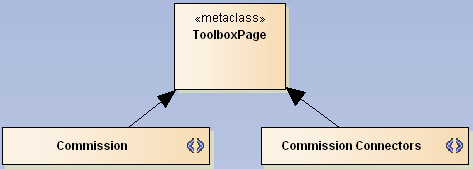
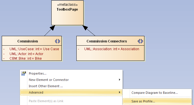
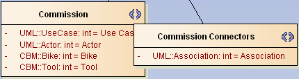
Let us start with the Commission diagram. The commission process shall deal with use cases and the Bike itself. Initially we have to place a new metaclass derived from Actor (same reasons as above for diagrams). This is to be renamed to ToolboxPage and will be used to create all the different toolboxes. Now we can place two new Stereotypes named Commission and Commission Connectors which both extend the ToolboxPage. The first will stand for the compartment to hold the relevant elements and the latter for the according connectors.
Filling the toolbox
The contents of the toolbox is defined by attributes representing the specific element and their default value which is used in displaying the textual description in the menu.
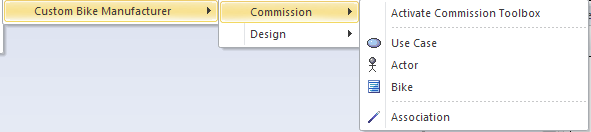
The Commission toolbox shall hold an Actor, a Use Case and the Bike from our profile. In the Commission Connectors we will just place an association. So we add an attribute UML::UseCase with default Use Case, UML::Actor with default Actor and CBM::Bike with default Bike to the Commission stereotype.
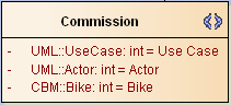
As you can see the standard UML elements are prefixed with UML and have an infix ::. The type of the attributes is a don’t care. int might look confusing. You are free to delete the type at all or to set it to string.
To access our Bike you need to prefix it with the profile name which we had chosen to be CBM7. In the Commission Connectors add UML::Association / Association.
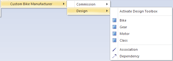
The creation for the Design diagram is analogously. We can reuse the ToolboxPage metaclass from the last step by dragging it onto our new Design diagram (drop as Link!). Then add new stereotypes Design and Design Connector both to be linked to ToolboxPage with extends. Add Bike, Motor, Gear and Class to the first and an Association and a Dependency to the latter.
Another quick test
Before linking the toolboxes to the diagram let us test the toolboxes. In order to do that we need to save the profiles (yes, plural) in yet another way. Open the first of the two new diagrams and from there the context menu (the one from the drawing pane, not from the project browser — orthogonality?). Here choose Advanced/Save as Profile... and put the file in mdgProf/diagrams with the same name as the diagram.
Repeat that for the second diagram. When we run the MDG creation “wizard” it is necessary to change the available profiles and tick Toolboxes.
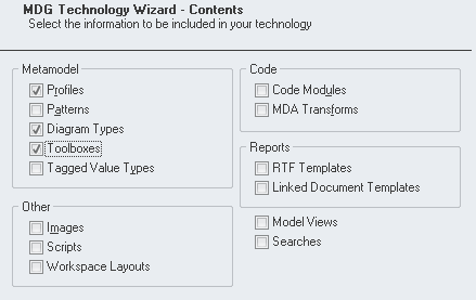
Now you will, additionally to profile and diagram, be asked to supply the toolboxes. Select the folder where they were saved and move them to the right side to the Selected Files.
You need to reload the newly created MDG and your toolboxes should be visible like this
and that
Ordering menus
As can be seen, the attributes in a single correspond to the order in the menu itself. But how is the order of the sub-menus determined? Well, this is EA. It’s the z-order of the menus on the diagram. Drag the two menu compartment stereotypes so they overlap:
As you can see the Commission Connectors overlaps Commission which means that it will appear below the latter. Try altering the z-order with the
 tool icons. Once re-saved the single toolbox compartments will appear in the new order.
Connecting diagram and toolbox
So we are almost done. The last part is easy but error-prone. All we need to do is to add a new attribute toolbox to each of our custom diagrams and set the default to the name of the toolbox profile. You need to be careful typing the names correctly. Since if you misspell one of them your profile will not work as expected. EA will not warn you in any way (just as we are used to that) but in the moment of deployment it will just fail. So for the <<metaclass>> of the Commission diagram stereotype add toolbox / Commission and for <<metaclass>> of the Design add toolbox / Design8.
We Are Ready!
The last thing to do before having a well served beer is
A final test
Save the CBMDiagrams package as profile (the package, not the diagram) and make sure the file goes to the right location. Now re-create the MDG and re-import as explained earlier. Open the Sandbox view and create both diagram types. When you hit the space bar on the Commission diagram you should see the toolbox below.
The Design should have one more element and one more connector.
3.4 Wrap Up
At this stage your mind should be clear about the connections between domain model, MDG profile, diagram types and toolboxes. Although we have just used the very basic elements it clearly comes to mind that such MDG extensions will improve modeling in different domains tremendously.
Just from a personal experience I would recommend to work with this basic toolset for a moment before trying more advanced stuff. It won’t hurt if you read a bit in chapter Versioning Profiles since that has a couple of pitfalls ready.
Enjoy your beer!