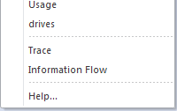
6. The Quick Linker
Here comes another nice gimmick. The quick linker (QL) is a special toolbox which allows context sensitive creation of links and eventually elements created at the other side of the link. This is very powerful for certain model parts. E.g. when creating a line of actions in an activity diagram.
In short the QL is defined by an Artifact element in your profile named QuickLink. This has a linked document with a CSV formatted text to define the (augmented) behavior of the QL whenever your MDG is active. That far things are easy and you can go ahead creating such an Artifact.
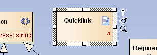
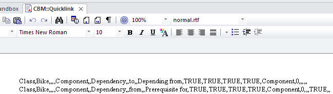
Use the Linked Document from the context menu and paste the following lines to it
1 Class,Bike,,,,Component,,Dependency,,to,,Depending from,TRUE,
2 TRUE,,,Component,,,,,,
3 Class,Bike,,,,Component,,Dependency,,from,,Prerequisite for,
4 TRUE,TRUE,,,Component,,,,,,
Don’t forget to save the changes (Ctrl-S), export the profile, re-generate the MDG and re-import it for testing: just drag the QL from a Bike element you created in the sandbox.
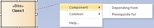
You now have the Component/Dependency from / Prerequisite for menu entries for a Bike element. Other or not stereotyped elements will not offer this menu. Choosing Prerequisite for will create a new Component
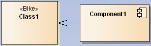
which has a dependency from the Bike.
6.1 Editing the Definitions
Before going into the details I like to explain how to edit the definitions for the QL a bit more efficiently16. So useful the QL is in practice so painful (even more) is it to create a custom one for your MDG. Here are a few tips.
As a first step you should change the document format of the linked document to landscape. At least it will help spotting wrong line breaks.
Next add a line before the first you placed in the above example and reuse that for your own QL definitions:
1 //Source Element Type,Source ST filter,Target Element Type,Target ST Filter,
2 Diagram Filter,New Element Type,New Element ST,New Link Type,New Link ST,
3 New Link Direction,New Link Caption,New Link + Element Caption,Create Link,
4 Create Element,Disallow Self connector,Exclusive to ST Filter + No inherit
5 from metatype,Menu Group,Complexity Level,Target Must Be Parent,Embed element,
6 Precedes Separator LEAF,Precedes Separator GROUP,DUMMY
To actually edit the definitions it is best to move them to a spreadsheet unless you like to count commas. The RFC for CSV is obviously ignored by anyone (I have not seen a single implementation which worked according to it). So the way to export as CSV and import CSV from file in the spreadsheet is not recommended. Vice versa the CSV export will also likely be scrambled and render to be unusable. I do it in three steps:
- Copy from linked document and paste into
Notepad++17. - Globally change comma to tab chars (using
\tas replacement). - Copy the whole text and paste to spreadsheet.
Now you have the data in a more handy format18.

As you can see the first comment line results in useful headers so you can modify the definitions a little bit easier.
Once you are done you need to move the results back:
- Select all cells from
A1toW*where*is the last row. It is important to include exactly theWcolumn which is called DUMMY! - Paste the cells to
Notepad++. - Globally change the tab char (again using
\t) to comma. - Copy the whole text and paste it to the linked document.
- Save the changes!
- Export the changed profile.
- Re-generate the MDG.
- Test the changes.
The above steps are error prone since you might forget one of them and loose your edits. But it’s proofed for me to be the least evil.
6.2 Testing the Quick Linker
Before going into details a short warning:
Now the Resources road is no longer that efficient. Instead the Advanced path from Extensions/MDG Technologies... is the preferred way. Since for testing we do need to restart EA it’s easier to set the path in the latter way which makes EA load the latest saved MDG automatically.
Further you should create a mini-model with a stripped MDG that mainly contains the QuickLink artifact and maybe a copy of your rest MDG. The QuickLink itself should contain only a single definition you are going to test. Only if this entry has been tested to work as expected it can go to the real profile. Also here you need to test again as the orchestration with many definitions can cause dissonances.
6.3 Operating Principle
One could probably write a whole book about the QL. So I can’t go into all bits and pieces. Anyhow, I’ll try to approach the QL with a couple of use cases.
UML already has constraints that certain connectors are only allowed between certain elements. The QL (as delivered by Sparx) not only respects these constraints but reduces the number of connectors it offers by the elements that are going to be connected to a most commonly used set. Also you will note that depending on the diagram where the QL is called the set of offered connectors differs. Though for the standard UML diagrams this is done by some internal magic you have the choice to introduce your own constraints.
Roughly spoken the QL is defined by a number of records that have filter constraints which influence the creation of its menu entries. Each record also has columns which flag the creation of links and eventually elements if the QL is dragged to an empty space on the diagram. While the pure filter entries work pretty much straight forward, the other columns may interconnect in a more complex way.
Link certain elements
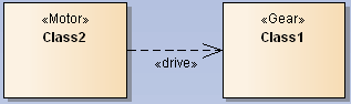
Let us start with the most trivial example which is going to offer certain connectors between elements from the MDG. To stay in the example domain we would like to say Motor will <<drive>> the Gear where the connector is of type Dependency. So we are going to offer a link named drives in the QL.
The first 4 columns describe the source and target elements to be (meta)type and stereotype. That would be Class19, Motor, Class and Gear. In columns H and I we place Dependency and drive for the connector type and stereotype. Column J becomes to20 so the dependency will point from Motor to Gear. The label in the QL menu is placed in K and we simply name it drives (to imply when linking that Motor drives Gear). Now we need to flag that a connector is to be created by placing TRUE in M. All other columns are left blank.
1 Class,Motor,Class,Gear,,,,Dependency,drive,to,drives,,TRUE,,,,,,,,,,
Once you re-generated the MDG and drag the QL from Motor to Gear you should see the drives entry somewhere at the end of the menu.
Vice versa when dragging from Gear to Motor you will not see the entry. But often it makes sense to offer the entry in that case too and have the dependency created as if it were done from Motor to Gear. To achieve that we add a modified second entry to the QL definition. B and D will be swapped (A and C are already the same). J must be change to from and K to driven by.
1 Class,Gear,Class,Motor,,,,Dependency,drive,from,driven by,,TRUE,,,,,,,,,,
So no matter whether you use drives or driven by the result will be a <<drive>> dependency from Motor to Gear.
You probably have already guessed that columns A to D work as simple filter. E.g. if you leave column B blank and add add such a definition line with <<support>> and supports then you will have a supports entry if you drag the QL from any class to a Gear. In case of the source being a Motor you will see both the supports and the drives menu entry.
If you leave all of A to D empty the connector is offered for any QL menu21.
Creating elements along with a connector
The initial example already introduced the creation of elements along with a connector. Now let us have a look at the details.
The columns A to D primarily act as filter. But additionally to the examples in the previous section the column N is set to TRUE which will instruct EA to offer an element creation menu if you drag the QL to an empty space. Now columns F/G additionally provide the information which element to create. Further column Q needs to define the name of the menu group (here Component).
Combining the previous two methods
If you want to both create an element when dragging the QL to an empty space and offering of link creation when dragged to an according element you can put that in a single directive.
So assuming that you want the Prerequisite/Dependency to be offered also when you drag from Bike to an existing Component you need to supply columns C/D (in this example with Component in C and D left blank) and K with an appropriate menu label (e.g. needs and supports or whatever you might think that fits here to create the dependency in either direction).
Filtering by diagram
As mentioned previously you can also apply a diagram filter. You do that if the QL entry shall be shown only in certain diagrams — or if you want to hide it in selected diagrams. For this purpose column E needs to be supplied with a semicolon separated list of diagram types. The following examples will be very (!) artificial but anyway, you will get the idea.
We just take the two connectors which create a component from the last section. Now we say that we want the Depending on only to appear in our Design and any Component diagrams while the Prerequesite for should be visible in all but class diagrams. To set the first filter column E must contain CBMDiagrams::Design;Component. The diagram from our MDG needs to be fully qualified. Since we did put the diagrams in the CBMDiagrams package this will be the prefix, the infix is :: and the suffix is the name of the diagram stereotype. Standard diagrams are that from the default list in section Custom Diagram. For the second connector we take the Logical (for class diagrams) and prefix it with an exclamation mark. This tells EA to match all but that one.
To test that the definition works you create/open a Design diagram first and place a Bike on it. When you drag the QL on an empty space you see just the Component/Depending from (since we explicitly told to show this connector on a Design diagram). And because it’s also a Logical (class) diagram the second connector is not shown.
The next test with a Commission diagram shows only the Component/Prerequisite for connector. This is because the diagram type is none of the first filter types and because it’s not a Logical the second one will show up.
The last test will be with a Component diagram and that will fit both criteria so you will see both connectors in the Component menu.
Summary of fields in the QL definition
As mention I will not describe all details of the QL but up to here it should cover at least 90% of all cases. Here is a summary of the columns used so far as well as some other (prefixed with a +) columns that might be of greater use.
A/B- These columns filter the starting element/stereotype. Only non blank entries are filtered.
C/D- In case you drag onto another element these columns define an additional filter analogous to
A/B. E- The diagram filter applies according to the diagram from where the QL is activated. A number of different FQN diagrams can be defined by separating them with a semicolon. Alternatively you can define a negative list by prefixing the FQNs with
!. F/G- These columns are only interpreted if you have set
Nto TRUE and you were dragging the QL to an empty space. In that case they define the element to be created. H/I/J- These columns are only interpreted if
Mhas been set to TRUE. In that case the QL will create a link as defined in these columns. J- We already had
toandfrom. But you can specify a number of different values here:- directed: association from source to target
- from: association from target to source
- undirected: association with unspecified direction
- bidirectional: bi-directional association
-
to: either a directed or undirected association, depending on the value of the
Association Directionfield in the options
K- The value in this column is shown in the menu in the case one a new link is being created (drag QL from element to element).
L- Like
Kbut when dragging the QL to an empty space. M- If TRUE the entry will be used in creating links (QL dragged from element to element).
N- If TRUE the entry will be used in creating elements (QL dragged from element to empty space).
+O- Set this to TRUE if you have left blank either
A/BorC/Dand want to forbid the creation of a connector to self. Q- The name of a menu group which is to be shown only when creating a new element.
+V- Sets a separator above the entry in the menu. However, I never noticed any influence on the menu with this set to
TRUE. YAEAB? W- The do-not-forget-me column you always forget and hence rendering your QL definition invalid.
For all other fields I kindly ask you to consult the help. Good luck.
6.4 Sub-Menus
If you need to group multiple stereotypes you can do that with sub-menus. E.g. we want to put the two tools SprayGun and Wrench in a sub-menu named Tools in the Design toolbox. In the according diagram we need to create a new stereotype named after the sub-menu (i.e. Tools). Here we place the two stereotypes CBM::SprayGun(UML::Class) and analogously Wrench. We need the extension since Tool extends Class and Package. Also we must add the attribute isHidden with an Initial Value of true.
The sub-menu itself must be added to the main menu with an attribute ToolMenu.
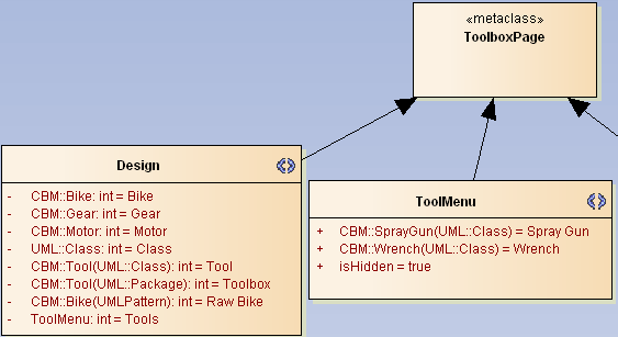
Once you regenerate the MDG the Design toolbox will show the new Tools entry and selecting that will open a popup with the the two tools showing up.
6.5 Debugging
Creating a QL definition will make you gnaw your keyboard more than once. When I meant that EA is not forgiving and you cross-check three times before finding the missing export/comma/entry the next day you will know what I’m talking of. So I can not offer much help, except some starting points when something does not behave as you would expect it.
- Did you save the linked document / export the profile (to the correct place) / re-generate the MDG? A quick peek in the MDG file itself (search for QuickLink) might help. But only if you followed my advise to work with only a single record in tests. If it does not contain what you would expect repeat the save/export/generate steps.
- Have you supplied all columns (including the dreaded
W-dummy) correctly? Cross check with a 2nd export from spreadsheet toNotepad++. - Are the filters correct? Try with a test record that has less filter criteria.
- In case of empty menu entries: cross check the according
K/Lcolumns. - In all other cases: start with a (similar) working record and modify it step by step.
I encountered the following message when loading a newly generated MDG:

It appeared for various reasons as duplicate lines, missing or too many commas and I don’t know what. The only way to trace it down was by un-/commenting lines until one line was identified to be the culprit. That’s quite annoying thinking of the possibility to see a message like “Error in Line x of the QL”. Sigh.
In any case: if it won’t work sleep over it. The next day often solves the issue by itself.