3. Heat Engines
All of the engines that utilises the Thermodynamics are called Heat Engines.These engines either External Combustion engines or Internal Combustion engines.
3.1 Petrol and Diesel Engines
These engines are primarily used on automobiles. These are internal combustion engines working on the direct power of the fuel. Thus it makes these engines more powerful.
3.2 Steam Engines
These Engines are typically not used in automobile industry. There are some extent of works which used Steam Power than engines. The steam engines produce more power than Internal Combustion engines , but most of the power is wasted on runtime.Therefore the resulting power ratio is very low.#Automobiles
3.3 Types of Automobiles
3.3.1 Light Vehicles
These type of vehiles are typically used in transportation of people rather than Goods. These light Vehiles can be categorised as follows.
| * Antique car | * Hatchback | * Quad coupé | * Drophead coupe |
| * Cabrio coach | * Hot hatch | * Retractable hardtop | * Executive car |
| * Cabriolet | * Hot rod | * Roadster | * Fastback |
| * City car | * Kei car | * Sedan (Saloon) | * Muscle car |
| * Classic car | * Large family car | * Shooting-brake | * Pony car |
| * Compact car | * Leisure activity vehicle | * Sport compact | * Notchback |
| * Compact executive car | * Liftback | * Sport utility vehicle | * Custom car |
| * Compact MPV | * Limousine | * Sports car | * Grand tourer |
| * Compact SUV | * Luxury vehicle | * Station wagon | * Hardtop |
| * Convertible | * Microcar | * Supercar | * Full-size car |
| * Coupé | * Mid-size car | * Panel van | * Minivan |
| * Coupé utility | * Mini MPV | * Personal luxury car | |
| * Crossover SUV | * Mini SUV | * Pickup truck |
We can categorise above into 7 simplified Groups known as follows,
- Saloon / Sedan Car
- Hatchback Car
- Coupe Car
- Convertible Car
- Estate Car
- Pickup Vehicle
- Van
3.3.1.1 Saloon / Sedan Car

These cars generally consists of 4 doors and occasionally 2 door.There are several variants of these type of car, usually combined into other Car Types. Luggage space has been allocated usually in back , while some rare models have Front Luggage Space. In those rare models Engine is usually located in Back or Middle.
3.3.1.2 Hatchback Car
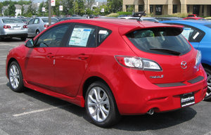
Especially these cars feature an additional door.Usually available in designs of 3 door(2 side, 1 hatch) and 5 door (4 side,1 hatch).The hatchback design allows to have more luggage space than ever. There were millions of Hatchbacks sold out since 1961. Renault 4 which was introduced by Renault became the first ever Million selling car of Hatchback model, with more than 8 million sold out.
3.3.1.3 Coupe Car
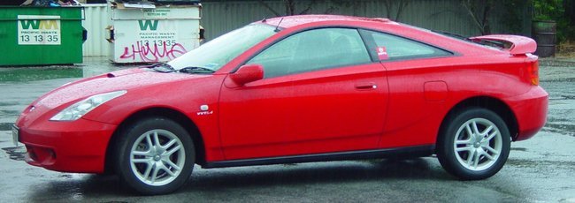
These cars feature a pair of seats in front row and no rear seat. Sometimes a pair of rear seats available. But in most cases there will be only a door per side.
3.3.1.4 Convertible Car
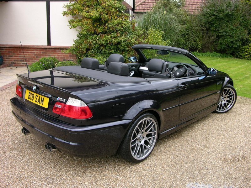
These cars usually referred to as Convertible . They feature a convertible roof top either Soft Top / Hard Top. There are several retractable Hard Top cars. These cars typically does not have large Luggage Space as much as of a Hatchback or a Saloon Car.
3.3.1.5 Estate Car
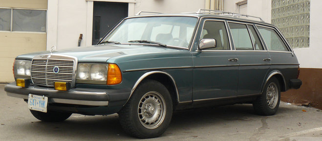
These cars have an additional Pillar than usual cars allowing the roof top to be extended allowing more space for luggage. These also have a additional door placed in back to give access to Extended Space. There are two pairs of seats.
3.3.1.6 Pickup Truck / Vehicle
These cars usually have two doors, some models have 4 door design. In addition these cars feature a Rear Space allowing Large Cargo Space.
3.3.1.7 Van
These type of Vehicle is mainly used to transportation of lighter goods than People, and sometimes used to transport People also.
3.3.2 Heavy Vehicles / Commercial Vehicles
These are type of vehicles typically used in transportation of Goods for commercial purposes. The main types of the Heavy Vehicles are categorised as
- Lorry / Truck
- Trailers
- Semi-Trailers
3.3.2.1 Lorry / Truck
These a medium weight vehicles. These are inbetween Weighs of 4.5 Tonnes to 10 Tonnes when fully loaded. These vehicles mostly have one or two axeles and Rear Powered.
3.3.2.2 Trailers
These are heavy weight vehicles composed of a Cab and a Trailer. The Cab contains Driver Seat and have Heavy Duty Engine.The Cab also features wheels that are Rear Powered. Usually a Cab is 4-6 Meters in Length. The Trailer which is about 10 - 13 Meters in Length attached to Cab via specially designed joints.
3.3.2.3 Semi-Trailers
These are medium or heavy weight vehicles which are attached to a Specially designed Lorry or Truck. These are attached via a dolly.
#Classification of Engines
3.4 By Principles of Working
The principle of working is a important classification of the engine. The engines work differently according to their specifications under these main principles of operation. They are
- Four Stroke Engine
- Two Stroke Engine
- Rotary Engine
3.4.1 Four Stroke Engine
3.4.1.1 Little History of Four Stroke Engines
The four stroke cycle was invented by Nikolaus Otto in 1870s and it is called Otto Cycle in respect to his invention. The invention was not patented properly and it went universal. The Otto Cycle is used in most of the latest automobiles because of its efficiency than other cycles.
Few years later Edward Butler came up with Petrol (Gasoline) Internal Combustion engine. Butler coined many of the terms of the 4 stroke engines. He invented further accessories to assist internal combustion and to increase efficiency. He was the first person to use the Term Petrol. He invented the following items in addition to Petrol Engine.
- Spark Ignition Plug
- Ignition Magneto
- Ignition Coil
- Spray Jet Carburetor
3.4.1.2 Mechanism of a Four Stroke Engine
The four stroke engine completes two rotations per power stroke. Thus resulting in 4 strokes. One Stroke is regarded as the movement of Piston from TDC to BDC or BDC to TDC. The Four strokes can be listed as follows
- Intake Stroke - Piston moves from TDC to BDC
- Compression Stroke - Piston moves from BDC to TDC
- Power Stroke - Piston moves from TDC to BDC
- Exhaust Stroke - Piston moves from BDC to TDC
3.4.1.2.1 Intake Stroke
In this state the inlet valve opens up paving way for fuel air mixure to enter the cylinder. During this course the piston moves from TDC to BDC. This makes enough room for Fuel Air mixure to get into the cylinder.
3.4.1.2.2 Compression Stroke
In this state the inlet valve closes down while the outlet valve remain closed. During this course piston moves upwards from BDC to TDC. This compresses the fuel air misture into the combustion chamber. Thus making the ignition more powerful.
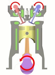
3.4.1.2.3 Power Stroke
In this stroke both valves remain closed.During this course the ignition or spark plug fires causing a spark inside the combustion chamber. It makes the compressed fuel air mixture to ignite with higher amount of power.Due to the ignition of the fuel the piston moves back to BDC from TDC.
3.4.1.2.4 Exhaust Stroke
In this stroke the outlet valve is opened to allow exhaust of the burned fuel air mixture. In this stroke the piston moves back to TDC due the action by the flywheel.During this action there is no power is being generated and the engine completely depends on the flywheel.
3.4.2 Two Stroke Engine
3.4.2.1 Little History of Two Stroke Engine.
By the time of invention of Four Stroke engine concept, there was no two stroke engine concept. The Two stroke engines invented shortly later. The two stroke engines complete the four steps of four stroke engine in two steps. Thus reducing much of the moving parts necessary. These engines do not feature a special lubrication material. The lubricator is mixed with fuel prior to fuelling or by the fuel pump. The ratio of the fuel and oil is 20:1. The oil is usually called 2T Oil.
3.4.2.2 Mechanism of a Two Stroke Engine
The two stroke engines completes one rotation per power stroke thus having a power stroke each time the piston head moves to TDC. The engine has high power outcome than Four Stroke engine due to power per stroke action and it makes the engine more fuel agnostic. The Two strokes are
- Compression and Power Stroke
- Intake and Exhaust Stroke
3.4.2.2.1 Compression and Power Stroke
The fuel is compressed to the combustion chamber by the piston in this stroke. As the piston reaches the TDC, the fuel is fired on the spark ignition concept and the ignited fuel forces the piston to move downwards and enter the next cycle.
3.4.2.2.2 Intake and Exhaust Stroke
As the piston reaches the BDC from TDC after the Power Stroke. The inlet valve and outlet valves are opened at the same time thus making the new fuel flow into the chamber replacing the exhaust gas. In a shortwhile the piston moves up for the next stroke preventing much of new fuel from escaping the combustion chamber.
3.4.2.3 Advantages of the Two Stroke Engine
- The Engine can be fitted to any angle.
- The Engines do not require a maintenance of a lubrication material.
- Produces high power than a Four Stroke engine.
3.4.2.4 Disadvantages of the Two Stroke Engine
- The engine requires high amount of fuel.
- The engine is more prone to friction and heat problems.
- Engine produces high amount of soot than usual.
3.4.3 Rotary Engines
3.4.3.1 Little History of the Rotary Engines.
During World War I & II , these types of Engines were constructed to provide much power than conventional four stroke / two stroke engines. These engines usually had pistons arranged in a circular order, thus connecting to a single crankshaft. These engines were unbalanced at higher speeds due to the heavy moving mass outside of crank case.
The earliest patented design was Atkinson Cycle which is now constructed as a Rotary Engine Cycle with higher efficiency. The patent was granted in 1886 in United States and earlier in European Countries.
In 1929 , Felix Wankel patented his design of a Rotary engine which reduced much of the problems in most of the rotary engines and other reciprocating engines. The working prototype was constructed as of 1955 and the license to produce the engines were sold to Automobile companies around the world. The Wankel engines were highly utilised by Mazda, a Japanese car manufacturer. The development of Wankel engines done by Mazda until 2011.
The Wankel Engines still today remain productive. The engine was vastly improved by Mazda. Due to the higher emission ratio than the Four Stroke engines, the Wankel’s Engine are abandoned in favor of Four-Stroke engines.
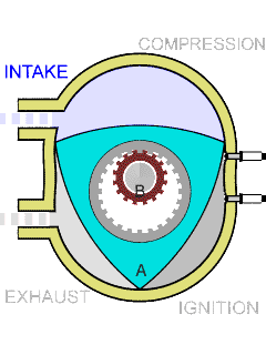
3.4.3.2 Mechanism of a Wankel Engine
The Wankel engine has a different concept than of a Reciprocating Engine. Wankel engines produce a lot of power per rotation of rotar, while cranks produce less amount of power. The Structure of Wankel engines allows to place simple inlets than a complex cams operating to intake and exhaust gas. The typical four strokes of a Four Stroke Engine happens in Wankel engine. The four strokes complete in one rotation.
The Wankel engine always have three simulantaneous actions out of intake,compress, ignite or exhaust happening in Three Chambers.Thus Wankel engine have a rotar with 3 faces, this makes Wankel engine to do 3 powered pushes per rotation.
The Wankel engines typically have apexes in the rotars which seal each chamber. The apex seals are not much durable as they slide along the Engine’s curves.
3.5 By Ignition Mechanism
3.5.1 Spark Ignition
In this mechanism, the fuel is spark ignited and the ignited fuel burns at a quick pace to produce power. This type of engines are mostly Gasoline based and do not carry a special fuel injector to compress the fuel.
3.5.2 Compression Ignition
In this mechanism, the fuel is compression ignited or burned by the high pressure of the combustion chamber. These engines do not require special mechanisms for spark generation, thus reducing parts of engine. This type of engines are mostly Diesel based and do not have a special ignition system in place to ignite the fuel.
3.6 By Cylinder
3.6.1 Single Cylinder Engine
The single cylinder engines are primitively used in Motor-bikes and less powered vehicles. The engines produce lesser amount of power due to the power stroke is 1:4 in any given occasion.
3.6.2 Double Cylinder Engines
The double cylinder engines are mostly used in few vehicles due to its instability of mechanism. These engines produce significant amount of power, but these engines face a great deal of instability due to counter-strokes of each cylinder in a cycle. To avoid this problem, another moving weight balancing part should be used in place. The most notable vehicle using the engine is, TATA Motors’ Nano cars. These engines have a power stroke ratio of 1:2, with a power stroke for a cycle completion of crank.
3.6.3 Triple Cylinder Engines
These engines are used in many vehicles during the 1940s to 1990s. The production of these engines were stopped after creation of stabilised 4 cylinder engines. The engines does not break the stability due to the third cylinder, and had been the most fuel efficient engine of all time.
3.6.4 Four Cylinder Engine
These engines are widely used since 1950s. These engines produce significant amount of energy enough to run a vehicle with heavy weight. The engine achieves a power stroke ratio of 1:1 per stroke in the engine. Thus producing more power than expected.
3.6.5 Six Cylinder Engines
These engines are unusual and mostly employed in sports vehicles to produce a great deal of power. Thus powering the vehicle to high speeds. The engines become more stable as the strokes happen more frequently and the efficiency of the whole output of the engine is awesome.
3.6.6 Eight Cylinder Engines
These engines are also unusual and mostly employed in sports vehicles. These engines are mostly configured in a V-type configuration to save space. Four cylinders per side is configured to save space in the V shape.
3.6.7 Twelve Cylinder Engine
These engines are rare and mostly used in special editions of sports vehicles. These engines produce high amount of power. These engines are usually configured in W mode to save space. This enables engineers to pack 12 cylinders in a space slightly larger than V8 engine. Each side of the engine carries 6 cylinders to a total of 12 cylinders.
3.6.8 Sixteen and Eighteen Cylinder Engines
These engines are ultra rare and no more produced due to need of more space and less efficient in producing great deal of power. These engines were also configured in W configuration. These engines were larger than typical W12 engines.
3.7 By Cooling Mechanism
There are different methods of cooling applied to the engines. In the beginnings the engines were air cooled and the heat produced by the engines was lower enough to be cooled by the air. In the midst time, there was a increase in the heat, and the liquid based cooling system was introduced to resolve the problem. At later times, Volkswagen group redesigned the air-cooled engine into “Volkswagen Beetle”. Current times, the liquid based cooling systems are used mostly in Cars and other big vehicles. Primarily, a special coolant is used as the liquid. Smaller vehicles like Motorbikes tend to use the Air cooling system.
3.7.1 Air Cooled Engines
These engines typically consist of fins along the cover of the engine cylinder to release the heat to the air. The fins are cooled by the air and then the engine is cooled. This cooling mechanism is mostly vulnerable to freezing and harder to work in hot environments.
3.7.2 Liquid Cooled Engines
These engines typically consist of a water line through the engine. The holes in the engine body allows the coolant to enter and leave the engine. The movement of the coolant is controlled by a thermostat with the help of a pressure pump.
3.8 Power of Engine
The power of a engine is usually measured in Horsepower addition to Watt. The method originated in the 19th Century, when Daimler used to compare the power of a Engine driven vehile to a Horse Driven Cart.
One Horse Power roughly equals to about 745 Watt. The horse power is usually denoted as BHP(Breaking Horse Power), It is the maximum power output of the engine.
{pagebreak}#Types of Engines
Throughout the history of the Automobiles Engines played a major role in controlling the speed.There were many experiments regarding the Engines after Renaissance. In the 19th Century historical breakthrough was done by Nikolaus Otto by inventing the four stroke Petrol Engine. There were many improvments to the engine parts since the invention of the Engine.
3.9 History of Engines
3.9.1 Steam Engines
In 18th and 19th Centuries there were inventions of Automobiles that run by Steam Power. Few of the constructions were proved to be successful regarding the efficiency of the system. The cars contructed using the steam engines were slightly bigger than Horse Driven Carts.
3.9.2 Earliest Internal Combustion Engines
The earliest internal combustion engines were built around 1830-1880. Those engines utilised various Technologies.Thus providing different efficiency ratios. These engines mostly used Plant Oils and sometimes Petroleum derived fuels to power the engines. The engines were primarily based with Ignition of the fuel until Rudolph Diesel invented the Diesel Engine which works by burning the fuel in high compress of 50,000 times of atmospheric pressure.
3.9.3 Improvements to Increase the Speed
As the commercial drigging of Fuels began in 1850s , there was a great percentage of inventors using the Petroleum derived fuels. Thus increasing the speed of the vehile by many times. Petroleum fuels consists of high calorie content. They provide high ignition and burning power.
3.9.4 Improvements in Fuel Usage
Until the invention of the Four Stroke Engine by Nikolaus Otto in 1880s the fuel usage of the engines were very high. The Hudson Engine which Hudson invented few years back in time when the Otto’s Engine invented worked with twice the Power of the previous engines with less fuel consumption. In 1880s Nikolaus Otto created Four Stroke engine with high efficiency by mising Air with fuel before ignition inside the Combustion chamber. The engine was not patented properly and the Four-Stroke mechanisms and Reciprocating Action went universal.
##Mechanisms of Engine Parts
3.9.5 Piston
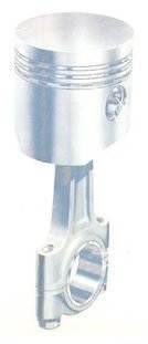
Piston moves up and down when Engine works.This creates a reciprocating movement. Piston consists of several parts which are used to modulate piston movements and increase efficiency. Piston usually consist of Piston head and Piston rings and other various accessories.Figure MOEP.1 shows the general structure of a piston.
3.9.5.1 Parts of a Piston
- Piston Head
- Piston Rings
- Gudgeon Pin
3.9.5.1.1 Piston Head
The Piston head is a important part which faces the combustion chamber. This is usually made up of elements which can withstand high heat with low malleablity.
3.9.5.1.2 Piston Rings
The Piston Rings wipeout the Oil of crank case and protect the heat gases from entering crank case. Thus preventing the mixture of Oil and Fuel. When piston rings wear off, the oil and fuel mixup in combustion chamber and forming more soot.
3.9.5.1.3 Gudgeon Pin
The Gudgeon Pin connects the Piston with Connecting Rod. The hole is located in the center of the Piston Head.
3.9.6 Connecting Rod
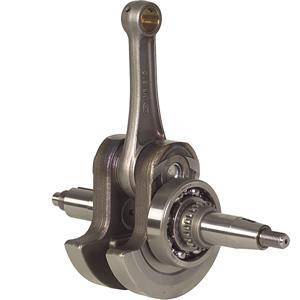
The connecting rod connects the piston to crankshaft thus involving in the power transmission to the wheels. The connecting rod moves in a rotating reciprocating motion. The connecting rod can be connected to crankshaft in two ways. Both can be observed in the Figures MOEP.1 and MOEP.2.
3.9.7 Crankshaft
The crankshaft plays a major role in transmitting the power and it connects the connecting rod to crank. Crankshaft involves in a rotating motion. One rotation of crank is called a Crank Angle. One rotation equals 360° of Angle.
3.9.8 Combustion Chamber
This is where the combustion takes place inside the cylinder. the space between the TDC and the spark plug. This is usually have volume of few cubic centimeters. It may be a larger area about 100cm3-2000cm3 in larger engines.The combustion area is small compared to cylinder capacities and it makes the ignition of the fuel to produce maximum power.
The combustion chambers can be further classified by the shape of the chamber.
- Pancake
- Wedge
- Hemisphere 4.
3.9.9 Valve Mechanisms
The valves operate in timing regarding the rotation of the piston. Thus connected to the mechanism by a camshaft and a sprocket chain. Cams located in the Camshaft open and close the valves. When both valves operate , they will be simultaneously open for a small period of time when piston reaches TDC in a Exhaust Stroke. This is called Valve Overlay.
3.9.10 Liners
The Liners are used in Automobile engines which are used for more time than usual to reduce the damage caused to the engine cylinder. These liners separate cylinder walls from touching the moving piston head. There are two types of Liners.
- Dry Liners
- Wet Liners
3.9.10.1 Dry Liners
The Dry Liners can be used in any kind of engines. These liners can fit any type of engine. As the coolant doesn’t have direct contact to the liner, it is less efficient in cooling down the engine. These liners have direct touch with the Cylinder Walls, thus providing great amounts of power to be used on. These Dry Liners are made from high quality Hardened Metal(High Grade Cast Iron) or High Carbon Steel.
The Dry Liners are placed into the Cylinder after heating the cylinder then cooled down to normal temperature. In some engines the Liners are cut perfectly and placed with Little Pressure.
3.9.10.2 Wet Liners
The Wet Liners are used in engines with high heat emissions to reduce the heat of the engine. As the liner have direct contact to the Coolant it is more cooler than dry liners. But the Wet Liners are slightly thicker than dry liners.
3.9.10.2.1 Advantages of Wet Liner
- Very fast cooling system.
- Installation and Uninstallation is easier than Dry Liner.
3.9.10.2.2 Disadvantages of Wet Liner
- Cooling liquid may leak into crankcase although water seals are placed at top and bottom.
- As it does not have touch contact with the Cylinder Wall, it is more weaker than Dry Liner.
3.9.11 Cylinder
TDC means Top Dead Center which is the Top Position, a Piston Head can reach and the BDC means Bottom Dead Center which is a Bottom position which Piston Head can go down inside Engine.
Piston moves from TDC to BDC ,while Crank finishes a Half-Cycle.The image on the left explains it.Whenever a Crank finishes a rotation , Piston moves from TDC to BDC and BDC to TDC. This movement is called Reciprocating Motion, while the Rotation of Crank is called Rotary Motion.The Reciprocating Motion and Rotary Motion happens simulantaneously inside the Engine.
For these actions to happen , Power should be given. When the Heat is given as Power, the Engine is called a Heat Engine. If the Power is generated inside it is Internal Combustion Engine and If the Power is generated outside it is called External Combustion Engine.
In the Internal Combustion Engines Gasoline(Petrol), Diesel are generally used Fuels, whereas Liquid Petroleum Gas is used in some Engines. Inorder to Ignite the fuel, Air is required.Therefore the Fuel is mixed with Air in a Separate Module and the Fuel Air Mixture is ignited inside the Combustion Chamber.After Ignition the Exhaust gas is expelled out from the Combustion chamber by Exhausting equipments.
When a Combustion cycle finishes the Engine should be powered again to return the Piston to the Starting Point as there is no Combustion takes place in the rest of the Cycle. A flywheel attached to the Crankshaft inorder to give back power Generated during Combustion Stroke.Flywheel mostly a three quarter wheel.
#Identifying Parts of Automobiles
There are parts in a Automobile which are necessary for the functions of the vehicle. Each component carries a prominent functionality which they correspond to.
3.10 Chassis of a Automobile
A chassis is usually the part of the vehicle where all of the parts of the vehicle are attached to. The chassis remains a stronger object frame made of hardened metals like High Carbon Steel. These chassis transfer the weight of the whole vehicle to the wheels through the axeles.
3.10.1 Engine / Electrical Motor
The Engine or the Electrical Motor is an important part of a automobile. It produces the power required to move the vehicle. The power throughoutput of the engines are usually measured in Horsepower or Watts, and its exactly termed as “Breaking Horse Power”.
The largest Breaking Horse power produced by a engine is 1200 by a Bugatti Veyron Engine in a W16 Configuration.
3.10.2 Transmission System
The transmission system is important as like as a Engine. The transmission system creates a connection to the engine and the wheels through the differential and propellar shaft. The transmission system’s final throughoutput is known as “Final Drive” and its delivered to the differential via Propellar shaft. The differential then distributes the power to the wheels in a asynchronous way(non-blocking).
3.10.3 Lubrication System
The lubrication system is essential in a Automobile to reduce friction between moving parts. Without a proper lubrication in place the engine would fetch into many ceases within a short time. The lubrication keeps the parts move smoothly by forming a thin layer around most of the moving parts and making them slip without much friction.
3.10.4 Cooling System
The cooling system is critically important to any heat engine to keep it cooled down. Otherwise the engine would go beyond the scales of permitted temperatures and break off. The cooling system consists of various parts to determine the temperature of the engine and keep it cooled down. The cooling system usually uses a special coolant which is resistant to freezing in low temperatures and with different viscosity levels.
3.10.5 Ignition System
The Ignition system is another important part of a engine. Without a ignition system in place, the engine cannot fire the fuel for burning in the correct order. Thus making the engine unusable for any purpose. The Ignition system fires the fuel at the right time according to the position of the piston and the speed of the piston. There are few methods used to determine the speed of the Piston and the position of the piston.
- Centrifugal Advance Mechanism
- Vacuum Advance Mechanism
- Computer Controlled Ignition
3.10.6 Suspension System
The suspension system is an essential part of user experience in a automobile. A Suspension system is required to keep the engine and passengers safe from the vibrations of the wheels and the engine.
3.10.7 Starting System
The starting system is also a necessary part of a automobile. It starts the engine from off state. The starting system checks various elements of the engine before kicking off the start process. It ensures that the engine starts in a safe procedure.
3.10.8 Braking System
The braking system of a automobile is very much important as a engine. The braking system makes the vehicle slowed down and stopped by applying brakes at various wheels. The braking system keeps the automobile stopped at certain circumstances. There are two types of braking components.
- Parking Brake
- Driving Brake
There are different types of braking based on the technology used in braking.
- Air based Braking System
- Liquid based Braking System