1. Introduction
We will start our journey by talking about an object many of us have seen; our planet has a similar shape to this object. If you guessed sphere, you were correct!
Spheres are all around us: from the many different kinds of balls used in sports to ball bearings in your bicycle. However, not many of us ever think about what makes a sphere a sphere? Would you be able to define an equation for the surface of a sphere? Have a go at this before moving on.
Theory: Describing a sphere
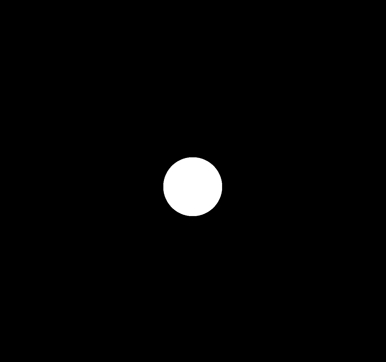
If you think about a white sphere on a black screen without any lighting, you are probably imagining something that looks like this:
Without any lighting, the image is no different from a white circle on a black background. We can describe the shape of a circle fully using its radius; we can do something similar for a sphere.
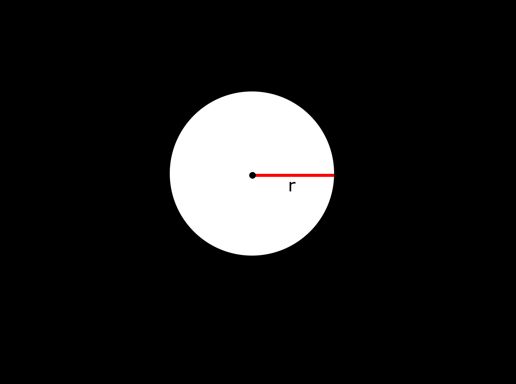
The radius is represented in the image above as the red line from the centre of the sphere (represented as the black dot) to the edge of the sphere. We can use the radius to define the points on a circle, using the following equation:
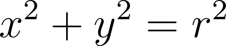
Notice that the word ‘on’ was in bold in the previous sentence: the equation above will give you  and
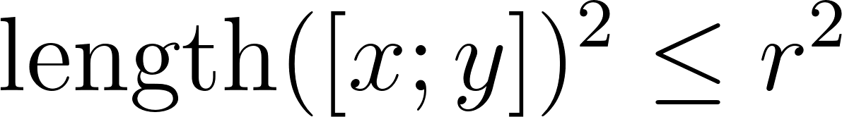
and  coordinates of points that are on the hull of a circle (i.e. its perimeter). In order to determine whether any coordinate is within a circle, we can slightly modify the previous equation:
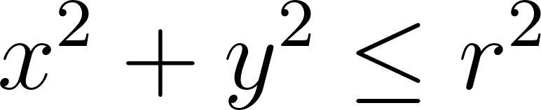
By replacing the equal sign by a less than or equal to sign, we can use the above inequality to test whether any point is inside a circle or not. If we use vectors to represent the and coordinates, we can simplify the above equation to this:
where  functions simply gives the length of the coordinate from the centre (by calculating
  ). We can apply a square root to both the left and right hand sides of the inequality, rearranging to give us the following:
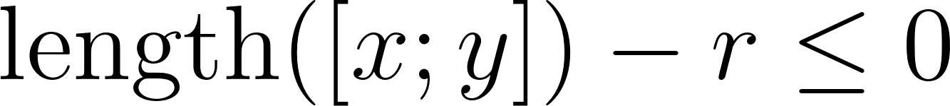
Fortunately, we can easily extend the equation above by using 3-dimensional vectors. The following equation gives the equivalent equation for a sphere (kind of like a circle in 3-dimensions?):
We will use this equation to develop our first SDF (Signed Distance Function) for a sphere primitive. I am calling these primitives as we can combine these shapes to make more complex objects.
Practical: Hello Shaders!
You are free to use any 3D library and coding environment that you want, provided it supports a modern shader based rendering pipeline. For this book, we will be using GLSL (OpenGL Shading Language) along with Visual Studio Code: these should be available on all major Operating Systems. In order to install Visual Studio Code for your system, please follow the instructions at this link: Download Visual Studio Code - Mac, Linux, Windows. Once you have done this, please install the following extensions that will make writing and evaluating our shaders a lot easier:
The first extension will allow us to quickly write our fragment shaders without having to deal with setting up the OpenGL pipeline in a programming language. The second extension tools to aid us in writing GLSL shaders.
After creating a file called ch1.fs in your editor, please type the code below into the file (please do not just copy-paste: learning is supposed to be an active process):
 1 precision mediump float;
 2
 3 // Provides us with the screen resolution.
 4 uniform vec2 u_resolution;
 5
 6 void main()
 7 {
 8     // Converts pixel coordinates values to be between 0 and 1.
 9     vec2 uv = gl_FragCoord.xy / u_resolution.xy;
10
11     // Colour of the background: currently set to have a red,
12     // green and blue value of 0 i.e. a black colour.
13     vec3 colour = vec3(0.0);
14
15     // Sets the final colour to be output to the screen.
16     gl_FragColor = vec4(colour, 1.0);
17 }
The comments in the code above should help with understanding what the code does. Essentially, we have a function called main() that tells OpenGL what colour each fragment should be. OpenGL provides us with some global variables like gl_FragCoord: this gives you the coordinate of the current pixel. The glsl-canvas provides us with more information by providing the uniform 2-dimensional vector called u_resolution, which gives us the width and height of the frame we are rendering to. We use these two values to set the uv variable, which transforms these coordinates into the range 0 to 1.
We then define a colour variable: this is a 3-dimensional vector where the first, second and third value represents the amount of red, green and blue in this colour (RGB values). In our code, all of these are set to 0.0, meaning colour represents black. Finally, we set the output variable gl_FragColor (note the American spelling of colour) to colour. If you now right-click your code, click Command Palette…, then search and execute the command Show glslCanvas you should be able to see the result of the fragment shader above: you should see a black screen.
[Challenge]
Try to play with the values of the
colourvector in the shader above. Your challenge is to:
Change the screen to be fully red.
Change the screen to be fully blue.
Change the screen to a more complex RGB colour (you can use an RGB colour picker online to find one you like).
[Answer]
This can be done by setting the red value of the colour vector to 1.0 and keep the green and blue values at zero:
vec3 colour = vec3(1.0, 0.0, 0.0);This can be done by setting the blue value of the colour vector to 1.0 and keep the red and green values at zero:
vec3 colour = vec3(0.0, 0.0, 1.0);Same as above but now using the specific values you found online. (Note: you are most likely going to find RGB values between 0 and 255. Just divide these values by 255.0 to get the correct value for the shader).
Practical: Sphere SDF and Ray Marching
Using the equation of a sphere that we formed above, we can add the following function above the main() function:
1 // SDFs
2
3 float sdfSphere(vec3 position, float radius)
4 {
5     return length(position) - radius;
6 }
The equation above defines the sphere implicitly using distance. Unlike triangle meshes, this does not immediately tell us which pixel should be coloured. To render such shapes efficiently, we use a technique called ray marching, where we move along a ray in steps determined by the signed distance function.
In real life, a light source emits light rays. Light rays travel in straight lines (if you ignore the impact of refraction and diffraction) and hit an object. The object absorbs different wavelengths in the white light (which is made up of many different colours of light) and reflect the light that is not absorbed: this is essentially the colour of an object i.e. a red object absorbs all the other colours of light except red. Eventually this light will reach our eyes where it will be absorbed by the rod and cone cells in the back of our eye, causing us to ‘see’ the world.
The above is a perfectly valid solution for the real world, however, as mentioned before we do not have such luxuries on computers. In order to deal with this limited power, techniques such as Ray Marching change the direction of light: they shoot light from the camera (or lens) into the world and choose the colours of the pixel based on what objects this ray of light hits (this idea is similar to how humans originally believed we see the world).
We will assume that each pixel on the screen is represented by a 2D grid in the 3D world we are representing. Each ray can be represented using two quantities: the vector representing the starting point of the ray and a unit vector representing the direction of the ray. We will then incrementally increase the length of this ray (i.e. ‘march’ the end of the ray forward) until it hits an object. Any point on a ray can be described using the following vector equation of a line:

where  is a point on the line,
  is the position where the ray starts,
  is the direction of the ray and
  is a variable controlling where the ray ends.
Based on all of the above, we can produce the following (please make sure that you place this code below the SDF function but above the main() function):
 1 // The distance where the near and far planes are.
 2 float nearDistance = 0.01;
 3 float farDistance = 30.0;
 4
 5 // Define a struct to store information about objects the ray has hit.
 6 struct HitInfo
 7 {
 8     float dist; // Distance returned by scene at the current sample.
 9     float totalDist; // Total distance travelled by the ray.
10     vec3 position;
11     int objectId;
12 };
13
14 // Define a struct to store material information about different
15 // objects.
16 struct ObjectMaterial
17 {
18     int objectId;
19     vec3 objectDiffuseColour;
20 };
21
22 // Forward define object materials
23 ObjectMaterial sphereMaterial;
24
25 // Our Ray Marching function based on the discussion above.
26 HitInfo rayMarch(vec3 rayStart, vec3 rayDirection)
27 {
28     // Start looking for a object hit at the near plane distance.
29     float rayStep = nearDistance;
30     HitInfo hitInfo;
31
32     // Loop controlling how many times we 'march' the ray forward.
33     // Here we march the ray forward a maximum of 100 times.
34     for (int i = 0; i < 100; i++)
35     {
36         // Find the location of the end point of the ray based
37         // on the equation above:
38         // p = r_start + (step * r_direction)
39         vec3 pointOnRay = rayStart + rayStep * rayDirection;
40
41         // Please ignore the error saying that the function scene()
42         // is undefined: we will implement this in the next code
43         // snippet.
44         hitInfo = scene(pointOnRay);
45
46         // Store the position where we potentially hit an object.
47         hitInfo.position = pointOnRay;
48         // Store the distance returned from the scene()
49         hitInfo.dist = hitInfo.dist;
50         // Store distance travelled by the ray.
51         hitInfo.totalDist = rayStep;
52
53         // Stop marching the ray if we exceed the far plane or hit
54         // at a distance less than the near plane.
55         if (hitInfo.dist < nearDistance || rayStep > farDistance)
56             break;
57
58         // March the ray forward by increasing rayStep.
59         rayStep += hitInfo.dist;
60     }
61
62     return hitInfo;
63 }
In the above code snippet, we make a reference to the scene() function; we will now define this function. This function essentially defines the layout of your scene i.e. allows you to define what objects are present in your 3D world, where they are etc. Please place the scene() function above the rayMarch() function:
 1 HitInfo scene(vec3 position)
 2 {
 3     // The coordinates where the centre of the sphere is. We
 4     // have set this to the coordinates (0.0, 0.0, 0.0).
 5     vec3 sphereCentre = vec3(0.0, 0.0, 0.0);
 6
 7     // The radius of the sphere.
 8     float sphereRadius = 0.5;
 9
10     // We now use the SDF function for the sphere to determine
11     // whether we have hit the sphere or not. Note the usage of
12     // (position - sphereCentre) instead of sphereCentre: this
13     // ensures that the sphere is translated correctly based on
14     // our current position.
15     float sphere = sdfSphere(position - sphereCentre, sphereRadius);
16
17     // Store information about the object we have hit. At the moment,
18     // the code below might seem unusual, however, imagine that we
19     // have many different types of objects in the scene, each with
20     // different material properties etc. The code below, when
21     // extended will allow us to correctly determine which object
22     // the ray hit.
23
24     // This min() function will be altered later to find the
25     // minimum distance of an object.
26     float finalDist = min(sphere, sphere);
27
28     HitInfo hitInfo;
29     hitInfo.dist = finalDist;
30
31     if (finalDist == sphere)
32     {
33         hitInfo.objectId =  sphereMaterial.objectId;
34     }
35
36     return hitInfo;
37 }
Hopefully, the above code along with the comments explains what each part of the function does. Finally, we will update the main() function to produce our first Ray Marched image:
 1 void main()
 2 {
 3     // Set object material properties.
 4     int maxObjectId = 0;
 5     sphereMaterial.objectId = maxObjectId++;
 6     sphereMaterial.objectDiffuseColour = vec3(1.0);
 7
 8     // Screen texture UV coordinates
 9     vec2 uv = 2.0 * (gl_FragCoord.xy /u_resolution.xy) - 1.0;
10     uv.x = (u_resolution.x / u_resolution.y) * uv.x;
11
12     // Setup scene.
13
14     // Set the default pixel colour to black.
15     vec3 colour = vec3(0.0);
16
17     // Near plane at 4.0 on z the z-axis i.e. 4 units out of the screen
18     // (z-axis pointing out of the screen).
19     vec3 cameraOrigin = vec3(0.0, 0.0, 4.0);
20
21     // Near plane at -1.0 on z the z-axis i.e. 1 units into the screen
22     // (z-axis pointing out of the screen)
23     vec3 rayDirection = normalize(vec3(uv, -1.0));
24
25
26     // Use Ray Marching to see which object the ray that goes
27     // through this pixel has hit.
28     HitInfo closestHit = rayMarch(cameraOrigin, rayDirection);
29
30     // Make sure we have not hit an object that is closer than
31     // the near plane.
32     if (closestHit.dist < nearDistance)
33     {
34         // if the closest hit object is the sphere,
35         // set the colour of this pixel to white.
36         if (closestHit.objectId == sphereMaterial.objectId)
37         {
38             colour = sphereMaterial.objectDiffuseColour;
39         }
40     }
41
42     // Output the colour from the Fragment Shader.
43     gl_FragColor = vec4(colour, 1.0);
44 }
The image below shows what you should be seeing on your screen. Congratulations! You have just produced your first Ray Marched image.
[Challenge]
Play with the radius of the sphere: does increasing or decreasing this have the effect you expected?
Play with the position of the sphere: does the result correspond to what you expected?
Change the sphere to be a red sphere instead of a white sphere.
Change the background colour to be a blue colour.
[Answer]
This can be done by increasing or decreasing
sphereRadiusin thescene()function.This can be done by changing
sphereCentrein thescene()function.You can set the sphere colour by altering the
sphereMaterial.objectDiffuseColourvariable in themain()function. To set it to red, you can do the following:sphereMaterial.objectDiffuseColour = vec3(1.0, 0.0, 0.0);Change the default value of the
colourvector tovec3 colour = vec3(0.0, 0.0, 1.0);. This will cause the black default colour to change to a blue colour.