5. Shaping Connectors
Basically the shape for connectors will be defined similarly to that for elements. So most of the previously explained methods can be used for connectors too (of course some – like compartments – do not make sense).
A major difference between both shapes is that elements all have that 100² unit frame. Connectors are not that easy. Shape Script distinguishes between different parts of a connector: source, target, the main connector line and the six labels. For each of them you can define a shape routine:
shape main { <block> }- will define what appears for the connector line.
shape source { <block> }- will define an extra shape at the source end of the connector.
shape target { <block> }- will define an extra shape at the target end of the connector.
shape <labeltype> { <block> }- will draw the
<labeltype>labels according to the statements in<block>. Here<labeltype>is one ofLeftTopLabel,MiddleTopLabel,RightTopLabel,LeftBottomLabel,MiddleBottomLabelandRightBottomLabel.
Now let’s see what happens when we put some code in these shapes.
5.1 The Connector
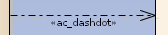
We will start with a simple example: using a dash-dotted line which – if my memory does not deceive me – is not used in UML. The following Shape Script is assigned to the base class dependency.
1 shape main {
2   SetLineStyle("dashdot");
3   MoveTo(0,0);
4   LineTo(100,0);
5 }
When used it will produce the following:
That was easy. But what happens when you actually draw something else? Well, let’s try by using the whole 100² units.
1 shape main {
2   MoveTo(0,0);
3   LineTo(100,100);
4 }
It looks like that the pixels below the connector are actually also used to draw something defined in shape main. Going a bit further using this code
1 shape main {
2   Rectangle(0,0,100,100);
3 }
will render as
As you can see the rectangle is rendered on the first section of the connector if there are less than 3 sections. Else it renders on the 2nd section.
5.2 Source and Target
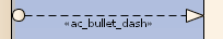
Now that the connector construction is clear let us have a look at the shapes at the endpoints. One of the samples from the Enterprise Architect help will do:
 1 shape main { // draw a dashed line
 2   noshadow=true;
 3   SetLineStyle("DASH");
 4   MoveTo(0,0);
 5   LineTo(100,0);
 6 }
 7
 8 shape source { // draw a circle at the source end
 9   Ellipse(0,-6,12,6);
10 }
11
12 shape target { // draw an arrowhead at the target end
13   StartPath();
14   MoveTo(0,0);
15   LineTo(16,6);
16   LineTo(16,-6);
17   EndPath();
18   FillAndStrokePath();
19 }
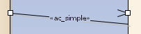
Here the connector is rendered as dashed line. The source will render a dot and the target a triangle. Finally it will look like this:
Now let us again endeavor a bit more at the endpoints. Let us simply produce a rectangle filling the 100² units and a small circle indicating the 0|0 coordinate:
1 shape source {
2   Rectangle(0,0,100,100);
3   Ellipse(0,-6,12,6);
4 }
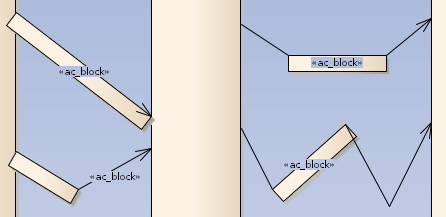
and analogously for shape target. Those will render as follows:
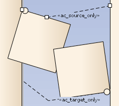
As you can see the source shape is rendered below the connector and the target above. I haven’t measured it, but it looks like both occupy 100² pixels. Further you can see that the connector itself will bend even inside the end-shapes.
Actually this means that you need to draw your shapes ±height around the 0-coordinate when you want some symmetrical endpoint. And your endpoint is top left of the shape meaning that you need to draw it reverse (so a possible arrow will point right to left with the tip at 0|0).
5.3 Labels
Simply let us see what happens when we use above methods to render labels:
 1 shape LeftTopLabel {
 2   Rectangle(0,0,100,100);
 3   Ellipse(0,-6,12,6);
 4   print("LeftTopLabel");
 5 }
 6 shape MiddleTopLabel {
 7   Rectangle(0,0,100,100);
 8   Ellipse(0,-6,12,6);
 9   print("MiddleTopLabel");
10 }
11 shape RightTopLabel {
12   Rectangle(0,0,100,100);
13   Ellipse(0,-6,12,6);
14   print("RightTopLabel");
15 }
16 shape LeftBottomLabel {
17   Rectangle(0,0,100,100);
18   Ellipse(0,-6,12,6);
19   print("LeftBottomLabel");
20 }
21 shape MiddleBottomLabel {
22   Rectangle(0,0,100,100);
23   Ellipse(0,-6,12,6);
24   print("MiddleBottomLabel");
25 }
26 shape RightBottomLabel {
27   Rectangle(0,0,100,100);
28   Ellipse(0,-6,12,6);
29   print("RightBottomLabel");
30 }
which renders directly as:
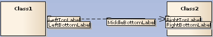
Actually the shapes are rendered as expected and scaled to the size of the containing text. One could expect the left and right top/bottom labels to be a bit more apart (the top being a bit more moved up), but that’s how it is. The top and bottom labels in the middle are placed directly at the same position which looks like a bug13.
5.4 Connector Drawing Methods
There a three drawing methods which are used only in conjunction with connectors.
SetFixedRegion(xStart,yStart,xEnd,yEnd)- defines areas along the connector where symbols should appear.
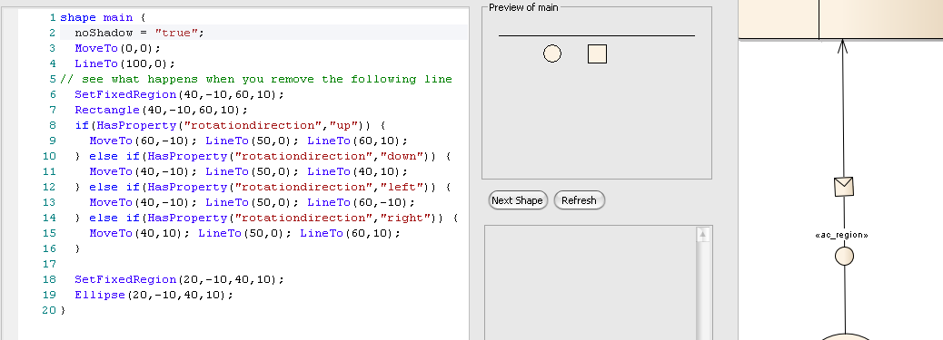
As you can see there are two regions defined. One for a square in the middle which shows a triangle oriented according to the general rotationdirection (see hash-tags below) of the connector. The second region simply shows a circle.
- `HideLabel(labelname)’
- will hide the accordingly named label which is a string holding one of the
<labeltype>values.
ShowLabel(labelname)- Reveals the hidden label specified by … according to the help. Well.
5.5 Attributes
Analogously to the attributes described in the Shape Attributes chapter here is a list for connectors.
endPointY, endPointX- Only used for the reserved target and source shapes for connectors; this point determines where the main connector line connects to the end shapes.
rotatable- Set to false to prevent rotation of the shape. This attribute is only applicable to the source and target shapes for line glyphs.