The Raspberry Pi Pico
The raspberry Pi Pico is a microcontroller board initially released by the Raspberry Pi Foundation as the ‘Raspberry Pi Pico’ in 2021. It is a board based around the in-house designed microcontroller chip the RP2040.
The RP2040 Microcontroller Chip
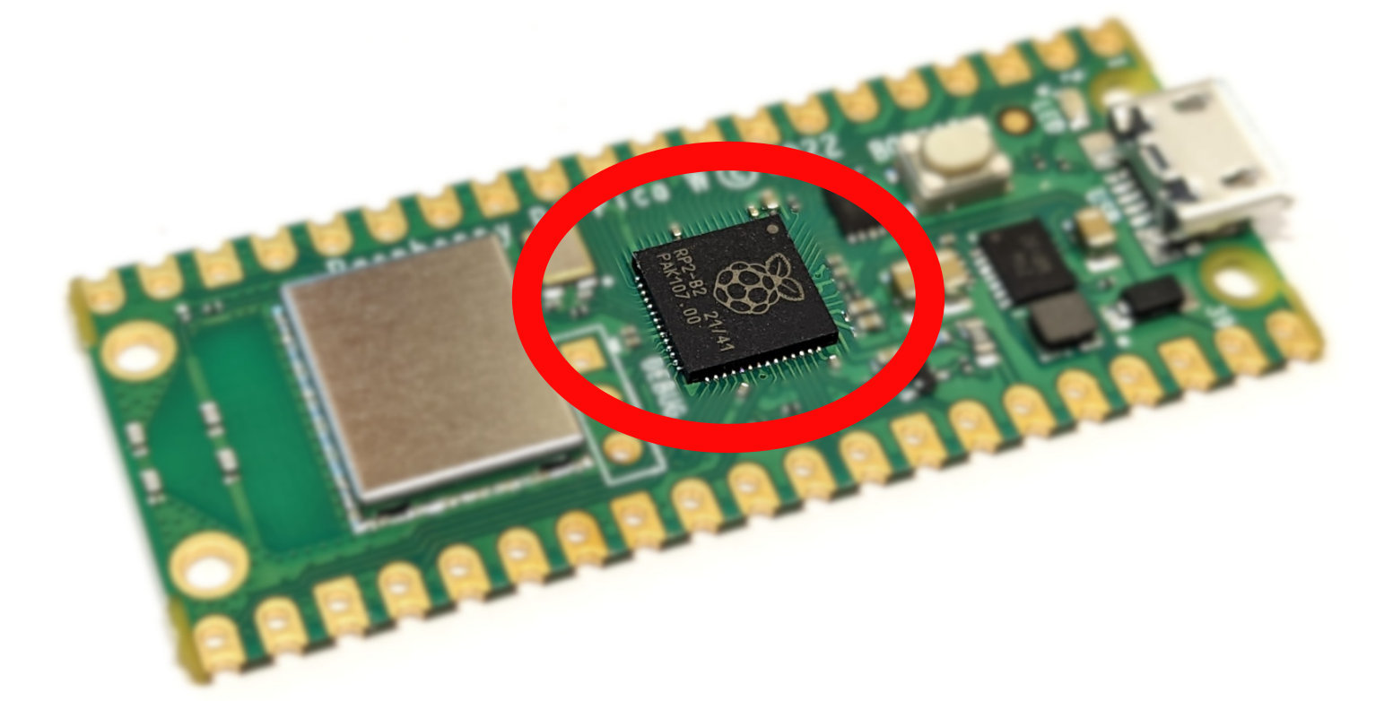
The RP2040 is the first microcontroller released by the Raspberry Pi Foundation. It was designed to deliver high performance, low power consumption and a wide variety of input / output options to provide beginner and hobbyist users with access to a modern and capable option for microcontroller based circuit boards.
It’s key features are;
- A Dual ARM Cortex-M0+ running at 133MHz
- 264kB on-chip SRAM in six independent banks
- Support for up to 16MB of off-chip Flash memory via dedicated QSPI bus
- A Direct Memory Access (DMA) controller
- Fully-connected AMBA High-performance Bus (AHB) crossbar
- Interpolator and integer divider peripherals
- On-chip programmable LDO to generate core voltage
- 2 on-chip Phase Locked Loops (PLLs) to generate USB and core clocks
- 30 General Purpose Input Output (GPIO) pins, 4 of which can be used as analogue inputs
It includes peripheral interconnects in the form of;
- 2 Universal Asynchronous Receiver/Transmitters (UARTs)
- 2 Serial Peripheral Interface (SPI) controllers
- 2 Inter-Integrated Circuit (I2C) controllers
- 16 Pulse-width modulation (PWM) channels
- A USB 1.1 controller with host and device support
- 8 Programmable Input/Output (PIO) state machines (PIO allows you to create additional hardware interfaces, or even new types of interfaces)
The chip can be purchased separately and has been incorporated into a number of different boards manufactured by organisations such as Arduino, Pimoroni, Adafruit, Sparkfun and Lone Dynamics. But arguably the most obvious board manufacturer is the Raspberry Pi Foundation itself.
The Raspberry Pi Pico W Microcontroller Board
At the end of January 2021, the Raspberry Pi Foundation announced the Raspberry Pi Pico as it’s first foray into the world of microcontrollers. The following year the Pico W was released that added (amongst other things) wireless functionality. The description below and pretty much any examples I describe will be using the Pico W.
The board includes the following features;
- 21 mm × 51 mm form factor
- RP2040 microcontroller chip designed by Raspberry Pi in the UK
- 2MB on-board QSPI flash
- 2.4GHz 802.11n wireless LAN option
- Micro USB B port for power and data (and for reprogramming the flash)
- 26 multifunction GPIO pins, including 3 analogue inputs
- 2 × UART, 2 × SPI controllers, 2 × I2C controllers, 16 × PWM channels
- 12-bit 500ksps analogue to digital converter (ADC)
- 1 × USB 1.1 controller and PHY, with host and device support
- 8 × Programmable I/O (PIO) state machines for custom peripheral support
- Supported input power 1.8–5.5V DC and several options for powering the unit from micro USB, external supplies or batteries
- The castellated module allows soldering direct to carrier boards
- Drag-and-drop programming using mass storage over USB
- Low-power sleep and dormant modes
- Accurate on-chip clock
- Temperature sensor
- Accelerated integer and floating-point libraries on-chip
The Pico provides minimum of external circuitry to support the RP2040 chip: flash memory, a crystal, power supplies and decoupling, and USB connector. Four RP2040 I/O are used for internal functions: driving an LED, on-board switch mode power supply (SMPS) power control, and sensing the system voltages. The Pico W has an on-board 2.4GHz wireless interface using 802.11n. The antenna is an onboard antenna formed as a resonant cavity by etching away copper on each layer of the PCB structure. The wireless interface is connected via SPI to the RP2040.
All in all the Raspberry Pi Pico established itself as an immediate realistic option for users of microcontrollers around the World. This in itself is a difficult thing in a dynamic market saturated with options.
Pinout
The Pico W has been designed to make available as much of the RP2040 functionality as possible.
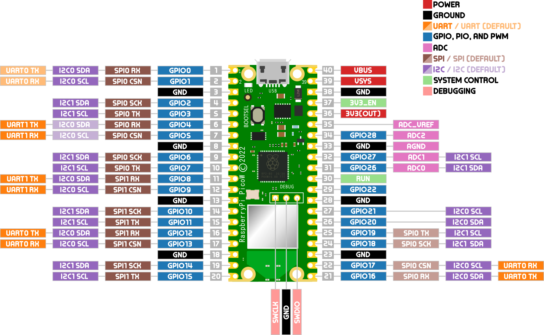
Apart from GPIO and ground pins, there are seven other pins on the main 40-pin interface;
- PIN40 VBUS is the micro-USB input voltage, connected to micro-USB port pin 1. This is nominally 5V.
- PIN39 VSYS is the main system input voltage, which can vary in the allowed range 1.8V to 5.5V.
- PIN37 3V3_EN connects to the on-board SMPS enable pin, and is pulled high (to VSYS) via a 100kΩ resistor. To disable the 3.3V (which also powers off the RP2040), short this pin low.
- PIN36 3V3 is the main 3.3V supply to RP2040 and its I/O, generated by the on-board SMPS. This pin can be used to power external circuitry. It is recommended to keep the load on this pin under 300mA.
- PIN35 ADC_VREF is the ADC power supply (and reference) voltage, and is generated on Pico W by filtering the 3.3V supply. This pin can be used with an external reference if better ADC performance is required.
- PIN33 AGND is the ground reference for GPIO26-29. There is a separate analogue ground plane running under these signals and terminating at this pin. If the ADC is not used or ADC performance is not critical, this pin can be connected to digital ground.
- PIN30 RUN is the RP2040 enable pin, and has an internal (on-chip) pull-up resistor to 3.3V of about ~50kΩ. To reset RP2040, short this pin low.
There is a pdf of the pinout available as an extra when you download the book from Leanpub. I recommend at the least printing out page size copy to have on the bench beside you when working or have it printed to poster size for the wall!
Powering the Pico
There are three main ways we can apply power to the Raspberry Pi Pico. The method used will depend on our application. We can power Raspberry Pi Pico from one of the following;
- The micro USB connector on the device
- The VBUS pin (40)
- The VSYS pin (39).
Powering from the USB connector is by far and away the simplest method, but not always desirable because of limitations of space or supply types.
If we provide a supply to the VBUS pin our Raspberry Pi Pico can take a voltage of between 1.8 and 5.5V, as it has an internal buck-boost regulator (which can regulate the output to a higher or lower voltage than its input). This will internally power VSYS via a Schottky diode, but we must be sure not to connect another power supply to Raspberry Pi Pico’s USB connector at the same time.
The VSYS pin is the main system power supply on Raspberry Pi Pico. From here the Raspberry Pi Pico generates its own 3.3V supply which is used to power RP2040, and also the 3V3 output pin (36). A safe way to add a second power source to Pico W is to feed it into VSYS via another Schottky diode. This will ‘OR’ the two voltages, allowing the higher of either the external voltage (or VBUS) to power VSYS, with the diodes preventing either supply from back-powering the other.