Connectivity
Arguably one of the most important features of a microcontroller is it’s ability to interface with systems outside of itself. Whether that be via a direct connection to the GPIO pins and their many Input / Output (IO) options, via WiFi or even the USB interface. There are a myriad of potential pathways for communication to sensors, other IT devices or directly to us mere humans.
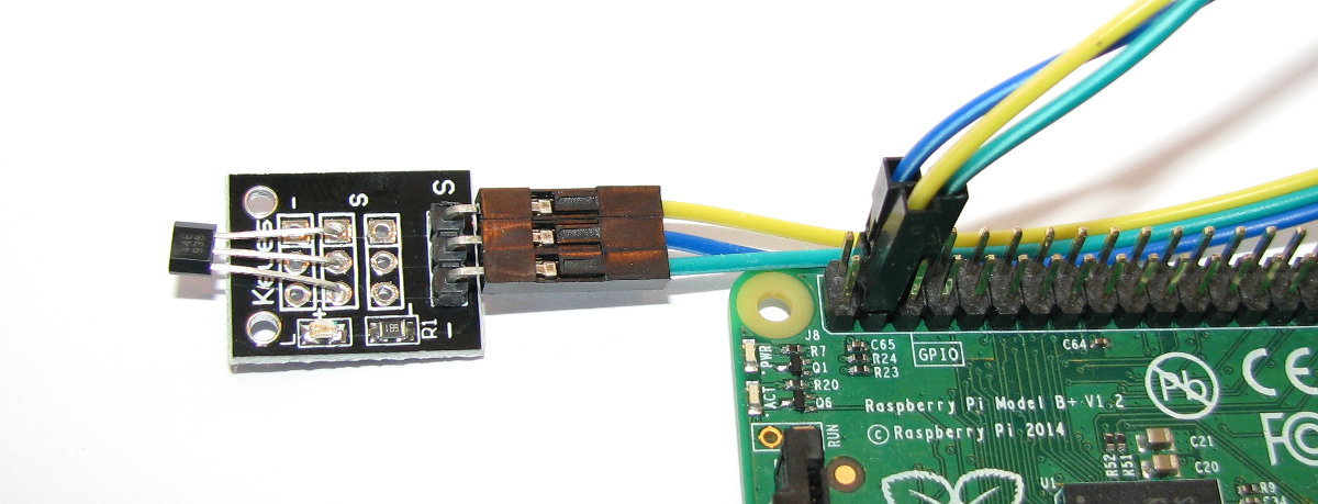
Connecting using Dupont Connectors
Event if you don’t recognise the name, if you’ve played around inside a computer there is a better than even chance that you’ve come across a Dupont connector.
They’re those small black plastic plugs that are used to connect things like the leds or USB connectors to your computers motherboard. They come in a range of different configurations and they are possibly one of the most underused mechanisms available for making ad-hoc connections between your Raspberry Pi Pico and external sensors or small boards. In fact, they can be used with a wide range of different areas and are limited only by the presence of a suitable connection point.
What are Dupont Connectors?
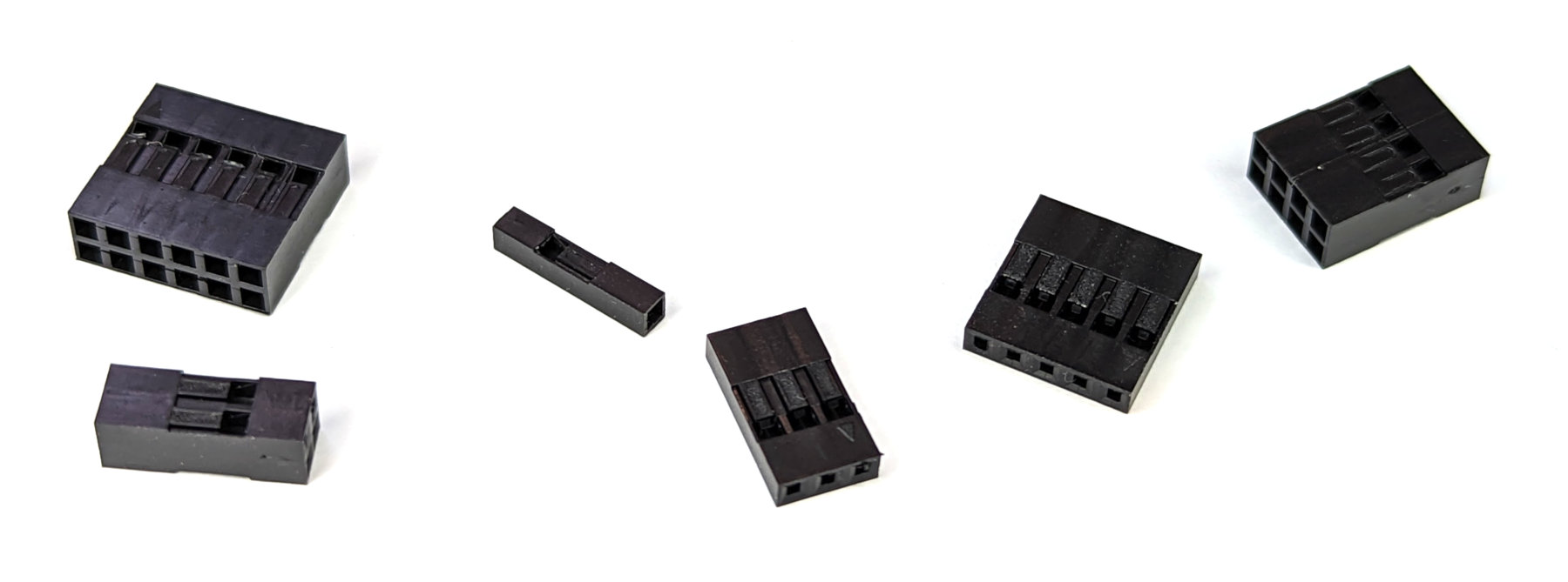
Technically there’s no actual industry term that calls out Dupont connectors. The style people commonly refer to as ‘Dupont’ is a variation of a black, low profile rectangular form with a 2.54mm standard pitch.
Off course the Dupont connector is just one half of a connector pair. The most common mating platform for them is to a header pin. A header pin (or simply a header) is a form of electrical connector. A male pin header consists of one or more rows of metal pins molded into a plastic base, 2.54 mm (0.1 in) apart.
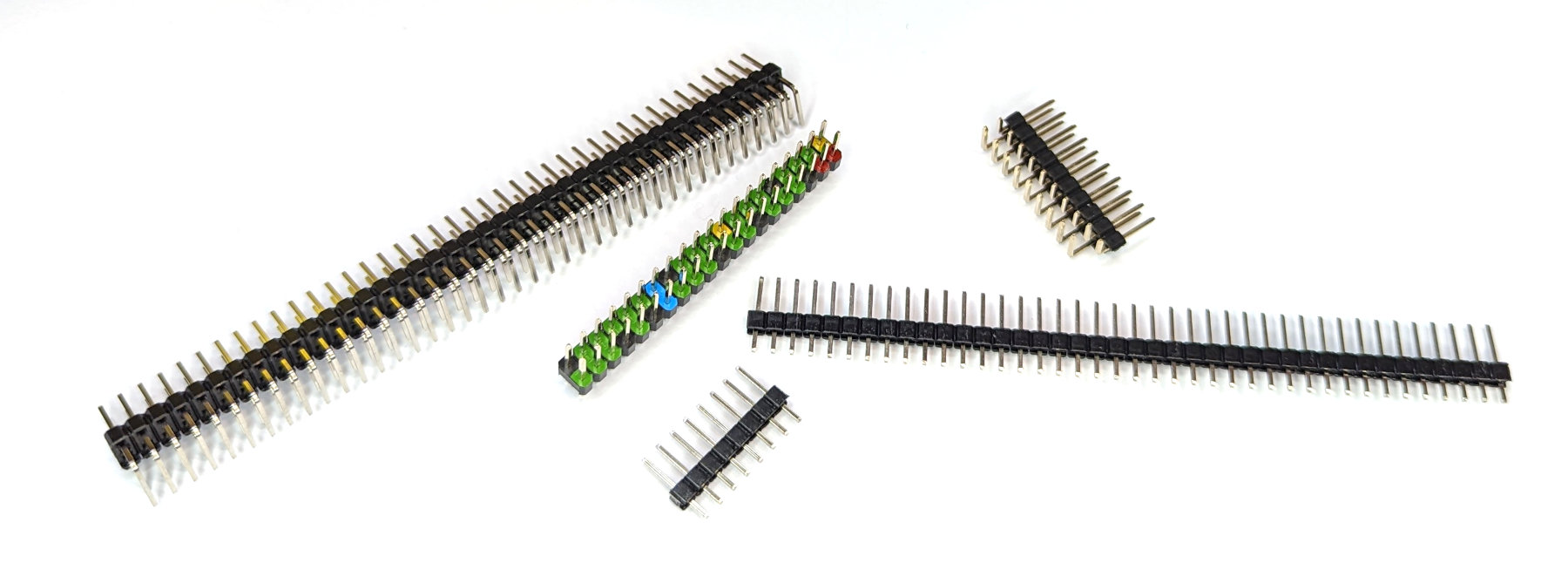
These can be straight, angled, single-in-line, dual-in-line and a myriad of other options.
The Dupont connector slips directly onto a header pin and because they share the same pitch (distance apart of the pins) of 2.54mm they can be similarly ganged together in a myriad of ways.
By far and away the simplest method of utilising this method of connectivity is to purchase bulk lots of the pre-made connectors. These can be male or female and commonly come joined to what is called ‘Rainbow Cable’.
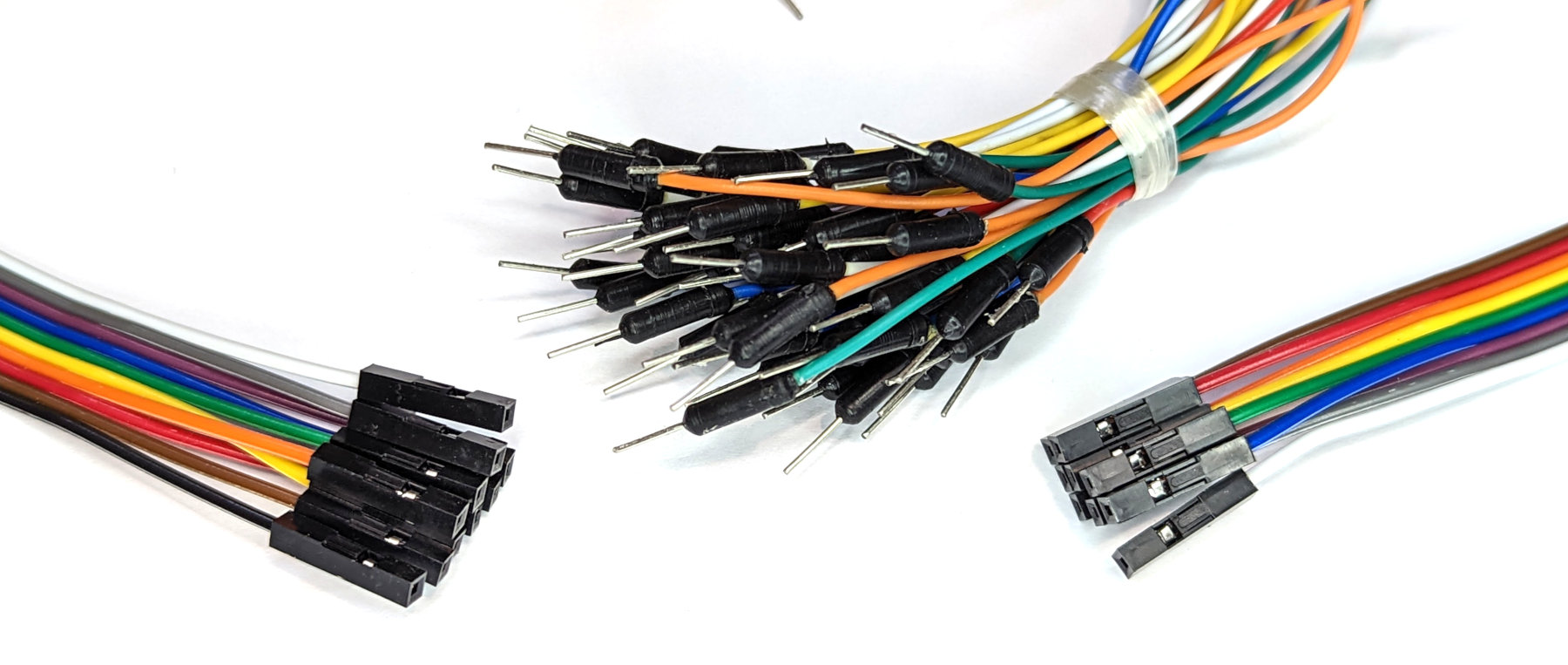
These are incredibly cheap and unless you have a very specific length that is required for a project, they are so easy to use they will quickly become ubiquitous for your project work.
Re-using Connectors
One of the cool things about Dupont connectors is that they can be adjusted by slipping the internal metal connectors out of their casings and placed into new casings. So if you have a set of cables in a three way connector, but the header that you want to connect to doesn’t have the connection points directly beside each other, not problem. Just use a small, flat bladed jewellers screwdriver or similar to gently bend up the plastic flap that is keeping the connector shroud in place. You can then slip the internal wire and connector out of the black plastic housing and place it into three separate single housings. Easy peasy.
Crimping Your Own Dupont Connectors
This is totally do-able and you will find all the materials to carry out the task online. However, as I mentioned earlier, unless you have a specific use for it, it’s probably just easier to utilise the pre-made versions.
However, if you have a need to construct your own connectors, the most important thing to know is that it’s a good idea to practice a few times before doing it for real. It isn’t too hard, but it’s worth having a few tries to get the feel of it. I’m not going to describe the method for constructing your own pins since there are a wealth of different methods and the written word can’t compare to a YouTube video of it being done and that’s not really my bag (maybe one day). I can advise that while there are plenty of tools for doing the job, with a little bit of practice you can get by with a sharp knife / scalpel for stripping the wires (for crying out loud be careful) and a par of needle nosed pliers. Certainly if you’re doing connectors on a regular basis or in an area where there needs to be a high standard of consistency and finish, proper tooling will be essential. But if you’re a hobbyist then why not?
Connectivity via WiFi
The Raspberry Pi Pico W includes an on-board 2.4GHz wireless interface which has the following features:
- WiFi 4 (802.11n), Single-band (2.4 GHz)
- WiFi Protected Access (WPA) 3
- Software enabled Access Point (SoftAP) which supports up to 4 clients
The antenna is a tuned cavity design which is licensed from ABRACON (formerly ProAnt). The wireless interface is connected via a Serial Peripheral Interface (SPI) to the RP2040 microcontroller.
It’s possible to use a standard Pico connected to an ESP8266 or similar to enable WiFi connectivity, but in enabling this I found there was more heartache than I cared to endure. With the release of the Pico W with WiFi built in, this should be the go-to option for connecting to a WiFi network if you’re using a Pico.
Using the network and socket modules
The network module includes functionality in the form of network drivers and routing configuration which is specific to the MicroPython. Drivers for the Pico W hardware is available within this module and it can be used to configure the network interface. Network services are then available for use via the socket module.
Scan for wireless networks
As an example of how the network module provides access consider the following code;
import network
wlan = network.WLAN(network.STA_IF)
wlan.active(True)
print(wlan.scan())
When run on a Raspberry Pi Pico W it will enable the network interface, scan for wireless networks and print them out
The import network line imports the network module.
wlan = network.WLAN(network.STA_IF) creates a WLAN network interface object with a client interface type (as opposed to an access point type, which would use network.AP_IF) .
We then activate the network interface with wlan.active(True).
Lastly we print out the results of a scan of available wireless networks with print(wlan.scan()).
The type of output that we would see might look something like the following;
Here there are three access points returned with the information apparently separated as ssid, bssid, channel, RSSI, security and hidden. Although, I’ll be honest and say that I know some of those networks and some of those ‘security’ and ‘hidden’ values don’t appear to be correct. More research could be required here.
‘bssid’ is the hardware address of an access point, in binary form, returned as a bytes object. We could use binascii.hexlify() to convert it to ASCII form if we got excited (we will do this in a future project collecting data from temperature sensors).
There are five values for security:
- 0 – open
- 1 – WEP
- 2 – WPA-PSK
- 3 – WPA2-PSK
- 4 – WPA/WPA2-PSK
and two for whether or not the ssid is hidden:
- 0 – visible
- 1 – hidden
Serve a web page
Serving up a web page is well within the Pico W’s capabilities. To do this we will need to active the network interface, connect to a wireless network and then create an http server with a socket connection and then listen for connections and serve up an HTML page.
This is definitely a more complicated process and we are going to make it slightly more so by using two external files to our main.py file. Don’t worry, there’s good reasons for doing so.
Firstly, create a file called secrets.py on the Pico with contents as follows;
Edit the file and put the name of the network (ssid) that you’re going to connect to and it’s password in the appropriate places. We are doing this so that when we write our main code, we don’t have to expose things that we would rather not when and if we share our main code.
Next create a file with the contents below and save it as index.html. This will be the web page that we will go to when connecting to the Pico W via the network.
<!DOCTYPE html>
<html>
    <head>
        <title>Pico W</title>
    </head>
    <body>
        <h1>Pico W</h1>
        <p>This is a very simple web page.</p>
        <p>REALLY simple.</p>
    </body>
</html>
Lastly, create the following file on the Pico and call it main.py. This will allow it to automatically start when the Pico is connected to power.
import rp2
import network
import machine
import time
import socket
from secrets import secrets

# Set country to avoid possible errors
rp2.country('NZ')

wlan = network.WLAN(network.STA_IF)
wlan.active(True)

# Load login data from different file for security!
ssid = secrets['ssid']
pw = secrets['pw']

wlan.connect(ssid, pw)

# Wait for connection with 10 second timeout
timeout = 10
while timeout > 0:
    if wlan.status() < 0 or wlan.status() >= 3:
        break
    timeout -= 1
    print('Waiting for connection...')
    time.sleep(1)

wlan_status = wlan.status()

if wlan_status != 3:
    raise RuntimeError('Wi-Fi connection failed')
else:
    print('Connected')
    status = wlan.ifconfig()
    print('ip = ' + status[0])

# Function to load in html page
def get_html(html_name):
    with open(html_name, 'r') as file:
        html = file.read()
    return html

# HTTP server with socket
addr = socket.getaddrinfo('0.0.0.0', 80)[0][-1]

s = socket.socket()
s.setsockopt(socket.SOL_SOCKET, socket.SO_REUSEADDR, 1)
s.bind(addr)
s.listen(1)

print('Listening on', addr)

# Listen for connections
while True:
    cl, addr = s.accept()
    print('Client connected from', addr)
    r = cl.recv(1024)

    response = get_html('index.html')
    cl.send('HTTP/1.0 200 OK\r\nContent-type: text/html\r\n\r\n')
    cl.send(response)
    cl.close()
Now run the main.py program. We should see feedback from the shell showing us the connection process and it should include the ip address of the Pico.
Put the IP address that appears in the shell into a browser that’s on our network and we should see a page giving us the happy news that we have created a web page!

At the same time we should see an indication in the Shell of the connection requests coming in each time we refresh the page.
There we go. We have just turned our Pico W into a web server! Not only that, but because we have named our program that does it main.py it will operate as soon as we plug in power.
Setting up a static IP address
Enabling network access to the Pico is a really useful thing. This has allowed us to access our device from a separate computer. But when we did it we relied on knowing what the IP address of the Pico was in order to enter that into our browser. The allocation of the address is dynamic and will be dependant on the configuration of our wireless network that is set up by our router. However, we can set up that address so that we know what it is going to be before hand. This is what is called a static IP address.
An Internet Protocol address (IP address) is a numerical label assigned to each device (e.g., computer, printer) participating in a computer network that uses the Internet Protocol for communication.
This description of setting up a static IP address makes the assumption that we have a device running on our network that is assigning IP addresses as required. This sounds complicated, but in fact it is a very common service to be running on even a small home network and most likely on an ADSL modem/router or similar. This function is run as a service called DHCP (Dynamic Host Configuration Protocol). You will need to have access to this device for the purposes of knowing what the allowable ranges are for a static IP address.
The Netmask
A common feature for home modems and routers that run DHCP devices is to allow the user to set up the range of allowable network addresses that can exist on the network. At a higher level we should be able to set a ‘netmask’ which will do the job for us. A netmask looks similar to an IP address, but it allows you to specify the range of addresses for ‘hosts’ (in our case computers) that can be connected to the network.
A very common netmask is 255.255.255.0 which means that the network in question can have any one of the combinations where the final number in the IP address varies. In other words with a netmask of 255.255.255.0, the IP addresses available for devices on the network ‘10.1.1.x’ range from 10.1.1.0 to 10.1.1.255 or in other words any one of 256 unique addresses.
Distinguish Dynamic from Static
The other service that our DHCP server will allow is the setting of a range of addresses that can be assigned dynamically. In other words we will be able to declare that the range from 10.1.1.20 to 10.1.1.255 can be dynamically assigned which leaves 10.1.1.0 to 10.1.1.19 which can be set as static addresses.
Because there are a huge range of different DHCP servers being run on different home networks, I will have to leave you with those descriptions and the advice to consult your devices manual to help you find an IP address that can be assigned as a static address. Make sure that the assigned number has not already been taken by another device. In a perfect world we would hold a list of any devices which have static addresses so that our Pico’s address does not clash with any other device.
For the sake of this exercise we will assume that the address 10.1.1.110 is available.
Default Gateway
We will also need to find out what the default gateway is for our network. A default gateway is an IP address that a device (typically a router) will use when it is asked to go to an address that it doesn’t immediately recognise. This would most commonly occur when a computer on a home network wants to contact a computer on the Internet. The default gateway is therefore typically the address of the modem / router on your home network.
We can check to find out what our default gateway is from Windows by going to the command prompt (Start > Accessories > Command Prompt) and typing;
This should present a range of information including a section that looks a little like the following;
The default router gateway is therefore ‘10.1.1.1’.
With all that information we are now ready to configure our static IP address.
Configure the static IP
Our network module and our WLAN class include an ifconfig method that uses all our gathered information’. We will need to declare it in the format wlan.ifconfig([(ip, subnet, gateway, dns)]).
When called with no arguments, this method returns a 4-tuple with the above information. To set the above values, pass a 4-tuple with the required information. For example:
Where 8.8.8.8 is a suitable DNS server.
To include it in the example of server our web server, we would slot it into the section where we are configuring the wlan settings;
wlan = network.WLAN(network.STA_IF)
wlan.active(True)
wlan.connect(ssid, password)
wlan.ifconfig(('10.1.1.110','255.255.255.0','10.1.1.1','8.8.8.8'))
Give it a try!
General Purpose Input / Output (GPIO)
The Raspberry Pi Pico has 26 multi-function General Purpose Input / Output (GPIO) pins available for connecting to external devices. 23 of them are digital only pins and three are also capable of acting as software selectable Analogue to Digital Converters (ADC). The voltage for the digital output is made available from the 3.3V rail.
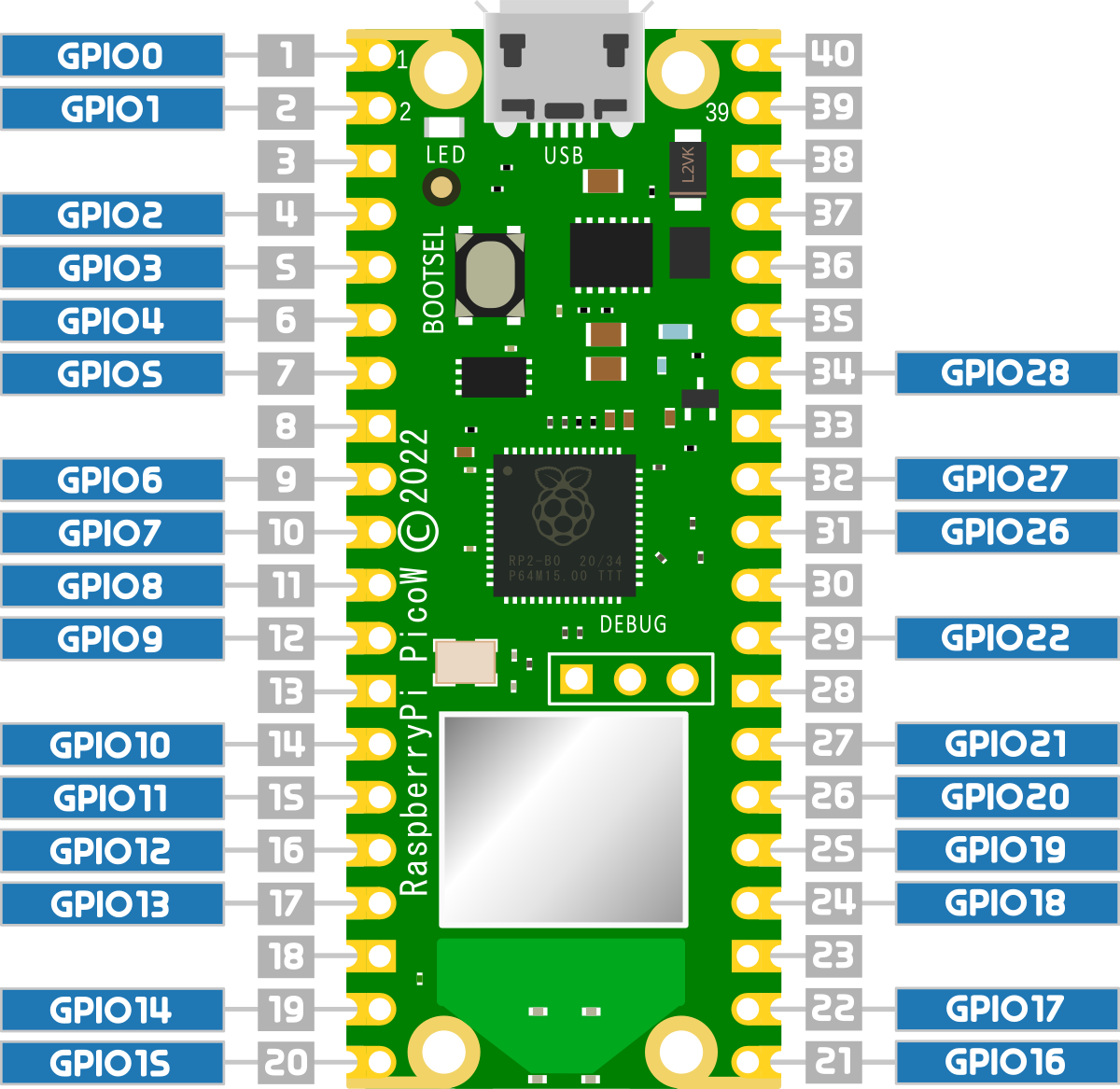
The observant reader will notice that the numbers above seem a little out of whack with the numbered pins on the Pico pinout. Here they go from zero to 28, but numbers 23, 24 and 25 are missing. Hence 26 total are exposed to the header pins.
The three missing pins (23, 24 and 25) in the sequence along with GPIO29 are used for internal board functions;
On the original Pico those functions are;
- GPIO23 OP wireless power on signal
- GPIO24 OP/IP wireless SPI data/IRQ
- GPIO25 OP wireless SPI CS when high also enables GPIO29 ADC pin to read VSYS
- GPIO29 OP/IP wireless SPI CLK/ADC mode (ADC3) to measure VSYS/3
And on the Pico W the functions are;
- GPIO23 OP Controls the on-board SMPS Power Save pin
- GPIO24 IP VBUS sense high if VBUS is present, else low
- GPIO25 OP Connected to user LED
- GPIO29 IP Used in ADC mode (ADC3) to measure VSYS/3
The exposed GPIO pins can be utilised as inputs or outputs for a range of different protocols and functions. These are in turn configured and enabled in software and can include;
- Serial Peripheral Interface (SPI): is a synchronous serial communication interface specification used for short-distance communication.
- Universal Asynchronous Receiver-Transmitter (UART): is a function for asynchronous serial communication where the data format and transmission speeds are configurable.
- Inter-Integrated Circuit (I2C): is a commonly used 2-wire interface that can be used to connect devices for low speed data transfer using clock and data wires.
- Pulse width modulation (PWM): is a method of reducing the average power delivered by an electrical signal, by effectively chopping it up into discrete parts.
- Analogue to Digital Converter (ADC): takes an analogue signal, such as a variable voltage level, into a digital signal.
Pull-up and Pull-down Resistors
When setting up a GPIO pin as an input, it is important to provide a stable state at the pin to enable a reliable reading. It’s easy to simply think that this has to occur when an important event occurs like sensing a high level from a switch or when triggering from a pulse, but the reality is that a GPIO pin is looking for a reading of one of two states. We can call them a range of different things like;
- High and low
- On and off
- 3.3V and ground
- 1 and 0
Whatever we call them the important fact is that the signal level can be distinguished between two different states.
This means that when we want to register when a high voltage occurs on a pin, first we need to know what the low voltage is. And visa versa. If we are looking to try and read when a pin drops to ground, first the pin needs to be able to recognise the 3.3V is the high point.
We accomplish this feat of knowing our reference points by using pull-up and pull-down resistors on our Pico.
What does pull-up and pull-down actually mean?
The answer to the question is kind of in the name, but that doesn’t necessarily make it obvious. It’s also really useful to frame the question by using an example, and in our case (since this is being written for a book about the Raspberry Pi Pico) we can use a GPIO pin on the Pico as our case study.
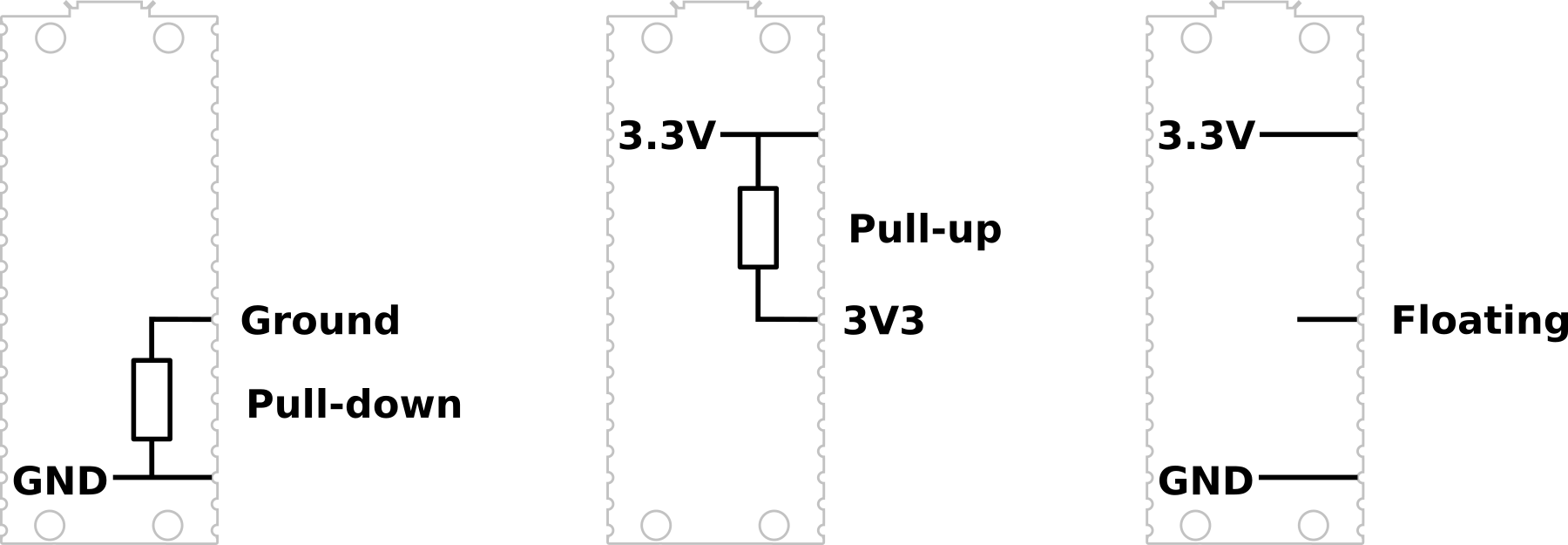
We like to talk about our ability to read either a high or low signal on our GPIO inputs, but the reality is that there are three states that our voltage measuring effort could result in. A low state that will typically be ground or 0V, a high state that will typically be about 3.3V, and a mysterious third state which is ‘floating’.
We can illustrate this by attempting to measure the voltages on our Pico.
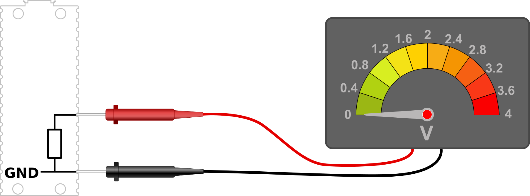
The low state
Using a meter to measure the voltage on our Pico, we can first ensure that there is a common reference point set by connecting our negative probe to a ground pin (here pin 23) and we can then measure the amount of voltage or potential difference is present between that ground pin and another (pin 33 shown here).
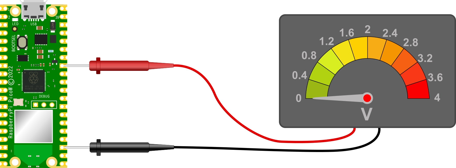
Unsurprisingly, we should read 0V. This is because the two ground pins are connected together on the circuit board and represent exactly the same voltage. Therefore the difference between them is 0V.
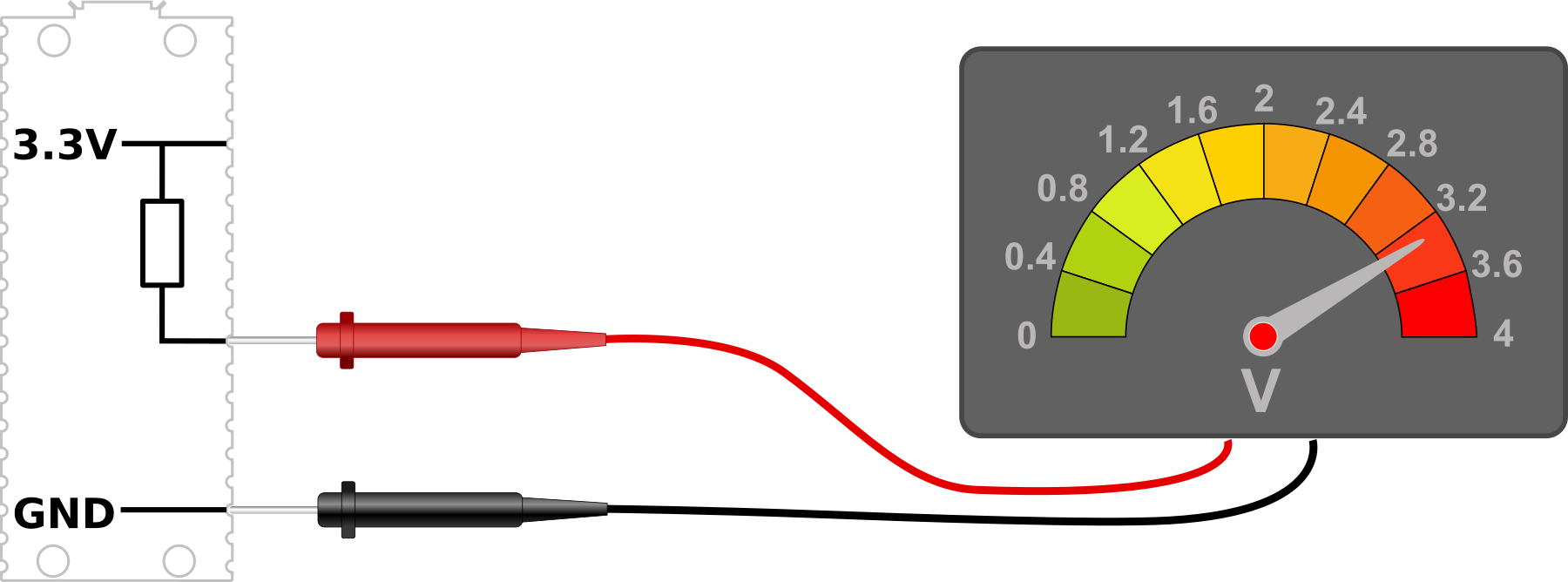
The high state
With our voltmeter measuring the difference between our common reference point of ground and the 3V3(OUT) pin (36), we are naturally going to read a voltage of 3.3V.
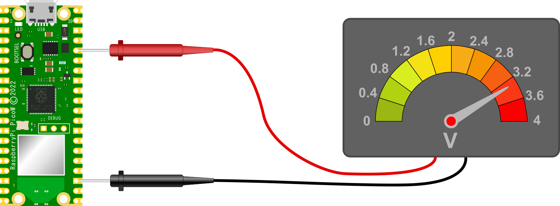
Again unsurprisingly we see 3.3V because there is a potential difference between the ground pin (23) and the 3V3(OUT) pin (36) of 3.3V
The floating state
And now to our ‘floating’ state. with our red lead removed from our Pico and floating in mid air, we have an uncertain reading on our voltmeter
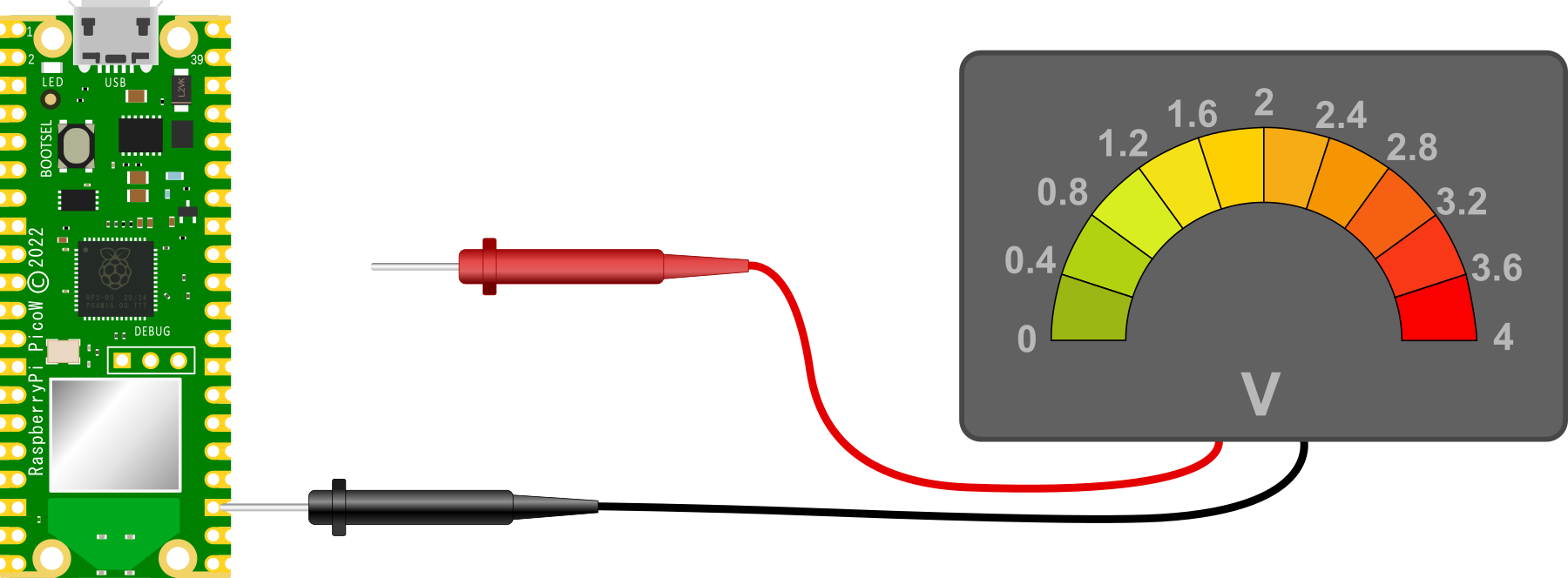
This situation is a bit like Schroedinger’s cat in the quantum state analogy. We can’t confirm if it’s alive or dead, so it’s both simultaneously. Except in this case, the reading is uncertain and we cannot state what it will be since there the meter is not fully connected to the circuit.
This floating state is the initial configuration of our GPIO pins on the Raspberry Pi Pico. Each one of them is essentially disconnected and as a result we can’t expect to read a steady voltage off them.
Pulling our pin
So to set our GPIO pins to a state where they have a reliable reference voltage we need to ‘pull’ the voltage either up or down so that in a resting state they read high or low.
A pull-up or pull-down resistor is connected so that the GPIO pin is connected to either ground or 3.3V via a resistance.
In some circuits this might be necessary to implement using discrete components, but the RP2040 microcontroller can configure a GPIO pin as either pull-up or pull-down internally and we just need to instruct it to do so via software. The resistance value in the pico is specified as being between a minimum of 50kΩ and a maximum of 80kΩ.
For example, in the PIR section of this book we set up our GPIO pin as an input and then we configured the pin as pull-down via the following code;
from machine import Pin

pir = Pin(22, Pin.IN, Pin.PULL_DOWN)
We can test our thinking by considering reading the voltage at our nominal GPIO pin with the Pin.PULL_DOWN configuration set. That will read 0V.
Conversely with the GPIO pin set to Pin.PULL_UP we will have the following circuit where we will read a voltage of 3.3V.
Once we have set the GPIO pin to its default state of high or low we can then go about the job of varying that pin to the alternate state via whatever input we choose. For example via a PIR or a common switch.
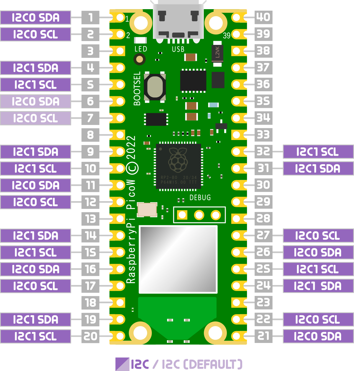
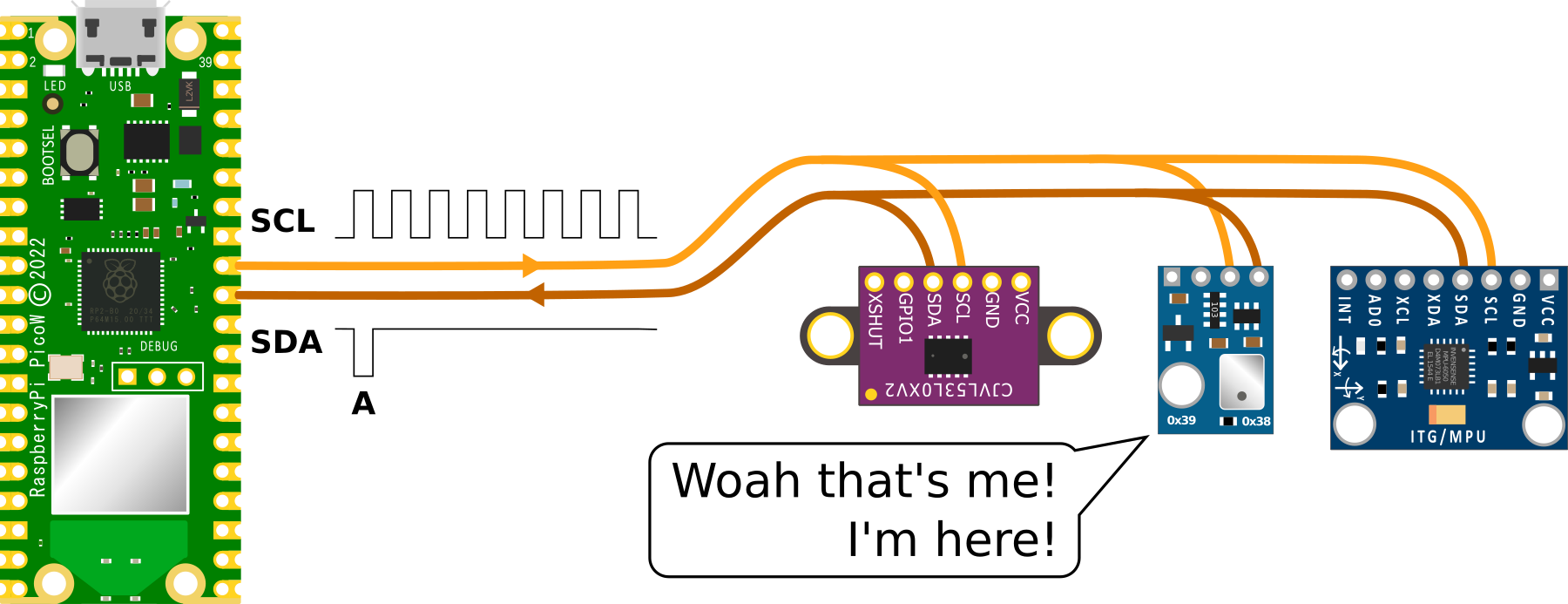
Inter-Integrated Circuit (I2C)
The Raspberry Pi Pico includes support to the I2C communications protocol through two I2C controllers which combined service a total of 12 separate connection pair options.
Right from the outset, this does not mean that we can hook up multiple devices (or string of devices) to multiple connection points that use the same controller. One device or string of devices per controller only. That means that we are limited to a total of 127 daisy chained devices per controller. That should be enough for a start :-).
I2C (Inter-Integrated Circuit) is a serial communication protocol that allows devices to communicate with each other over a shared bus. It was developed in the 1980s by Philips Semiconductors as a way to reduce the number of wires needed to connect devices, and has become widely used in a variety of applications.
I2C uses a two-wire interface, consisting of a serial data line (SDA) and a serial clock line (SCL). Devices that use I2C are called ‘slaves’, and they are connected to a ‘master’ device (usually a microcontroller or processor) through these two wires. The master device controls the communication by generating the clock signal and sending/receiving data on the SDA line.
I2C is a very useful protocol because it allows multiple devices to communicate with a single microcontroller or processor using just two wires, making it well suited for use in embedded systems and other applications where space and resources are limited. It is also relatively simple to implement, making it a popular choice for many applications.
How does I2C work?
The master device controls the communication by generating the clock signal and sending/receiving data on the SDA line. The slave devices are connected to the master device through the SDA and SCL lines, and they respond to the commands and requests of the master device.
Here is a brief overview of how I2C works:
- The master device starts the communication by pulling the SDA line low while the SCL line is high and then pulling the SCL line low as well, indicating the start of a new data transfer.

- The master device then sends a 7-bit slave address followed by a read/write bit, indicating whether it wants to read data from or write data to the slave device.

- If the slave device recognizes its own address, it sends an acknowledgement (ACK) by pulling the SDA line low. If the slave device does not recognize its own address, it does not send an ACK and the communication ends.
- If the master device wants to write data to the slave device, it sends the data byte by byte, followed by an ACK from the slave device after each byte. If the master device wants to read data from the slave device, it sends a request for data and the slave device responds by sending a byte of data followed by an ACK from the master device.


- The communication ends when the master device sends a stop condition by pulling the SDA line high while the SCL line is high.

Finding and I2C devices connected to the Raspberry Pi Pico
On the Raspberry Pi Pico, I2C is implemented using a hardware peripheral called the I2C controller, which is part of the Pico’s RP2040 microcontroller. The I2C controller is responsible for generating the clock signal and managing the communication between the Pico and I2C slave devices.
To use I2C on the Raspberry Pi Pico, you will need to import the machine module and use its I2C class.
The following code that demonstrates how to scan for I2C slave devices on the Raspberry Pi Pico and print the addresses of the detected devices.
import machine

# Create an I2C object with the specified SDA and SCL pins
i2c = machine.I2C(sda=machine.Pin(22), scl=machine.Pin(23))

# Scan for slave devices on the I2C bus
devices = i2c.scan()

# Print the addresses of the detected devices
print(devices)
This code creates an I2C object using the SDA and SCL pins 22 and 23, respectively, and uses the scan() method to detect slave devices on the I2C bus. It then prints the addresses of the detected devices.
Serial Peripheral Interface (SPI)
What is the Serial Peripheral Interface protocol?
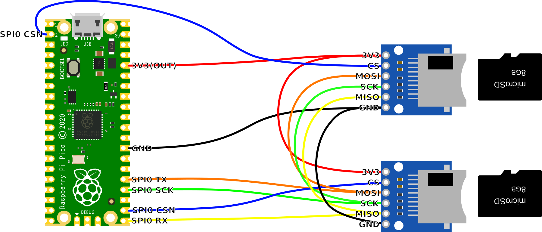
A Serial Peripheral Interface (SPI) is a type of serial communication protocol used to transfer data to devices such as sensors, displays, and other peripherals. It is a full-duplex, synchronous communication protocol that uses four wires to communicate;
- A clock signal (SCK)
- A data out signal (Master Out Slave In, or MOSI - connected to the Pico SPI TX line)
- A data in signal (Master In Slave Out, or MISO - connected to the Pico SPI RX line), and
- A chip select signal (SS or CS or CSN).
How does SPI work?
In an SPI system, there is one device that is designated as the master, and one or more devices that are designated as slaves. The master device generates the clock signal and controls the communication by asserting the chip select signal for the slave device it wants to communicate with. The slave device responds by sending or receiving data over the MISO and MOSI lines.
A simplified description of how an SPI communication cycle works is as follows;
- The master asserts the chip select signal for the slave device it wants to communicate with.
- The master sends a command or data over the MOSI line to the slave.
- The slave receives the data and sends a response over the MISO line to the master.
- The master receives the response and de-asserts the chip select signal, signalling the end of the communication cycle.
This process can be repeated multiple times to transfer multiple bytes of data. The clock signal determines the speed of communication, with higher clock speeds allowing for faster data transfer.
SPI is similar in function to I2C (Inter-Integrated Circuit), but where SPI is at a disadvantage in terms of the number of wires used and a more limited number of connected devices, it has the advantage of much higher data transfer speeds.
How is SPI implemented on the Raspberry Pi Pico?
The Raspberry Pi Pico has two built-in SPI controllers courtesy of the two SPI channels on the RP2040. There are a choice of pins that may be used for the SPI signals, but you can only define one set per channel. As well as this, each device will need it’s own dedicated chip select connection.
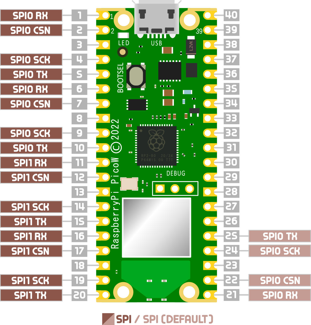
Looking at the pinout for the Pico we can see that there are three chip select connectors for SPI0 and two for SPI1.
In fairness, it is possible to use the process known as ‘bit-banging’ to simulate an SPI interface on any GPIO pin, but we will need to take into account a slower speed and increased susceptibility to noise.