IV. Effective use of arc42
In chapter II you got to know arc42 by means of a simple example. For all arc42 sections you learned why it exists and what you can communicate with it.
In this section you might encounter conflicting advice: We do that with intention:
Let’s look at one concrete example: In section IV-1 we recommend the use of activity diagrams, but also the use of numbered lists. What sounds like a contradiction is intended to demonstrate various alternatives. In some places we will offer explicit criteria for making a specific selection, in other places, the choice is just a matter of taste. In case of doubt, please use the incremental approach: get feedback on a (coarse or preliminary) version of a arc42-section and adjust detail or notation based on the feedback (see Tip III-2).
This Chapter Remains To Be Completed
IV.1 Tips for introduction and goals
IV.1.1 Requirements Overview
Tip IV-1: Compact summary of the functional requirements and driving forces.
For several readers, arc42-section 1.1 will be the first thing they learn about the system.
Here you should express the business or project goals clearly and concisely. Give a brief overview of what problem the systems solves.
Note: Sometimes a requirements document relates to more than the single system that we describe in the architecture documentation.
If project scope and system scope are different, you should focus only the parts of the requirements that apply to this system.
Our rule of thumb:Less than one page, if possible. This page may contain a diagram if it supports the content. You should reference requirement documents if present.
Note: in some cases you probably need to write more:
- For systems with complex or extensive business requirements
- For systems without an existing (and reasonable) requirements documentation
Tip IV-2: Limit yourself to the essential tasks and use cases
In arc42 section 1.1, document a few fundamental use cases, features, procedures, processes or user stories (however you call those in your organization).
Limit yourself to a level of abstraction so that also outsiders are able to get an overview of the major tasks in a short period of time.
Tip IV-3: Highlight the business goals of the system
You should ensure that the business goals (objectives) are explicitly known. Actually, this should already be in the project contract, or in the requirements specifications … Business objectives are often more global and on a higher level compared to the more detailed system requirements.
Tip IV-4: Create an overview by grouping or clustering requirements
In order to provide an overview of the functions of your system, describe in your architecture documentation only the importance of these groups without going into detailed individual requirements.
The figure below shows an example: some ellipses group (cluster) multiple requirements or use cases. Some of them can be found in the table

| Building block | Description |
|---|---|
| Import Handling | Import-from-Mandator, Import-von-PrintShop, Import-from-Scanner, Import-from-CallCenter, Import-from-CAMS, … |
| Configuration | Configure-Person, Configure-PrintJob, Configure-ScanOCR, Configure-Reports, … |
Tip IV-5: Make sure you can reference (existing) requirements
In case you are referencing existing requirements in the architecture documentation, e.g. to justify a design decision, you need to make sure that these requirements can be identified uniquely, by a short key or something similar.
- Sometimes you can take those IDs from the requirements documentation.
- If your requirements are managed by a tool (e.g. an issue tracker), you can use those ID’s - with some tools you even have stable URLs.
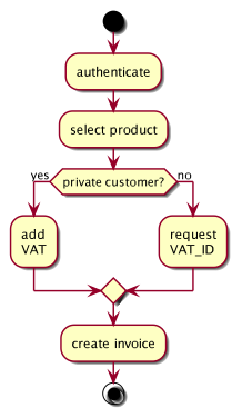
Tip IV-6: Use activity diagrams to describe functional requirements
Tip IV-7: Use BPMN diagrams to describe functional requirements
In case your stakeholders perceive activity diagrams as too technical, you may use BPMN diagrams. The Business Process Model Notation explicitly addresses business stakeholders and can therefore be seen as an alternative to activity diagrams for describing business or technical processes.
Tip IV-8: Use a numbered list to describe functional requirements
![]() In this context you could also use a numbered lists as simple and pragmatic
way to describe activities, procedures or processes. The activity
In this context you could also use a numbered lists as simple and pragmatic
way to describe activities, procedures or processes. The activity
mentioned earlier could then be exemplified as follows:
- Authentication
- Select a product
- Check customer type
- Private customer, add the VAT (value-added tax)
- Business customer, ask for the VAT-ID
- Create Invoice
In case you have to describe concurrent processes, activity diagrams see tip IV-6 are the better choice
Tip IV-9: Use (semi) formal text to describe functional requirements
We used PlantUml (http://plantuml.com/) to create the activity
mentioned earlier: This open source
tool generated the diagram from the following textual description:
@startuml
start
:authenticate;

:select product;

if (private customer?) then (yes)
  :add\nVAT;
else (no)
  :request\nVAT_ID;
  endif

:create invoice;
stop

@enduml
Activities are between: and;, branches can be read as pseudo code and that way you combine the benefits of plain text with graphical representation.
IV.1.2 Quality Goals
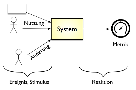
![]() You must know the relevant quality requirements of your stakeholders -
preferably concrete and measurable. As an architect you need to know
your success metrics …
You must know the relevant quality requirements of your stakeholders -
preferably concrete and measurable. As an architect you need to know
your success metrics …
Tip IV-10: Use ‘exemplary business process models’ to describe functional requirements!
You can describe functional requiremens as “exemplary business process model”. They describe processes from the viewpoint of stakeholder and the tools and materials used.
Please consider the following example:
You can find additional information (… in German…) here.
Tip IV-11: Always work with explicit quality requirements
Requirement documents often focus on functional requirements, quality goals remain implicit (and therefore unclear, uncertain, interpretable …). However, you can captures the desired quality attributes relatively easy, by using scenarios. See next tip.
Tip IV-12: Explain quality requirements through scenarios
Scenarios explain in short sentences how the system should react in certain situations at certain events. There are several categories of these scenarios:
- Usage scenarios: how does the system react in certain types of use? In the example below: The execution time of an HTML-validation must not exceed 5 seconds.
- Change scenarios: how does the system behave when you change it or extend it? This allows you to identify how fast certain kinds of changes or extensions can be done or how much effort is probably needed.
- Failure or downtime scenarios: how does the system behave when a serious problem occurs, such as the failure of central hardware or software components.
Scenarios may relate to a variety of possible quality attributes, which are structured hierarchically by current quality models (e.g. ISO-25010). Some examples:
Change scenarios:
- A new algorithm for the routing of robots in a high-bay warehouse needs to be integrated. One developer can make this change within 4 hours including the modifications of the build and the unit and integration tests
- At the end of the year, the output format of the (annual) reports must be adjusted to fit new legal requirements. All required data are already in the database and the changes affect layout, formatting and aggregations. These changes can be fully implemented within at most 60 person-hours.
Usage scenarios
- The system selects the necessary data for the XY-process within 1 second (up to 100 concurrent users) or within 3 seconds (up to 1,000 concurrent users).
- After switching on, it takes at most 4 seconds until the navigation system accepts input from the GUI.
Tip IV-13: If you do not get quality requirements, make your assumptions explicit
We experience again and again that development teams lack explicit quality requirements from customers or key stakeholders.
That leaves the quality goals implicit leading to a high risk of misunderstanding and dissatisfaction of all the people involved.
Our advice: Make explicit assumptions about appropriate quality goals, based on your knowledge and experience - take an educated guess.
Together with 2-3 team members, you could write down those assumptions as scenarios and discuss these educated guesses with your stakeholders. Such assumptions are always better than having no explicit quality requirements!
Tip IV-14: Use checklists for quality requirements
With its hierarchical representation (see ISO 25010 figure below,
With its hierarchical representation (see the diagram below), the ISO standard 25010 provides a good checklist for top-level quality “topics”.
As a more practical alternative, consider the the arc42 subproject arc42-quality-requirements for more than 60 real-world examples of quality requirements.
TODO: insert link to quality requirements
Some common “quality topics” are:
- availability
- modifiability
- maintainability
- reliability / robustness
- performance (runtime efficiency)
- security
- safety
- usability
- testability
Tip IV-15: Use examples to work out quality goals together with your stakeholders
The arc42-QA subproject contains more than 50 exemplary quality scenarios that you can use as a template for defining quality goals and requirements of your system.
Tip IV-16: Describe only the top 3-5 quality goals in the introduction
Use brief explanations with scenarios (see tip IV-12), not only keywords.
All the other qualities goals and requirements can either be found in the requirements specification or in the quality tree in arc42 section 10.)
Tip IV-17: Combine quality goals with the action points of the “solutions strategy” section
Sometimes you take decisions based on concrete and specific quality requirements. In such cases, it helps to document these quality goals and the resulting decisions in a consolidated table. We propose that you put such a table into the arc42 section 4 (solution strategy). In arc42-section 1.2 (quality goals), you then only add a reference.
Tip IV-18: Describe the detailed quality requirements in arc42 section 10
Describe the complete detailed quality requirements in arc42 section 10, not here (in the solution strategy, section 4)
You should give a detailed overview of all quality requirements (quality tree and scenarios) in arc42 section 10 (quality tree). There you can also show there the relationship between the quality goals.
IV.1.3 Stakeholder
Content Explicit overview of all the stakeholders of the system, i.e., all people, roles or organizations who
- should know the architecture or
- must be convinced of the architecture,
- work with architecture or code (e.g., use interfaces),
- need the documentation of the architecture for their own work
- make decisions about the system and its development
Motivation
You should know the people who are participating the project or are concerned by it, otherwise you will experience surprises later in the development process. These stakeholders determine among other things the scope and level of detail of your work and results.
Tip IV-19: Search broadly for stakeholders
In order to give you some ideas, we came up with a frightening long list of possible stakeholders studying [Clements-11] as well as from looking at the template arc42. All these people or roles may have an interest in the architecture or its documentation …
Analyst, Business Analyst, (other) architects, auditor, supervisory board, project sponsor, public authority, council, build manager, business manager, database administrator, end users, enterprise architect, developer, external service providers, external partners, department, technical administrator, hardware engineer, hotline / support, infrastructure planners, integrator, IT strategy, lawyer, configuration manager, control panel, customer, steering committee, management, neighboring systems, network administrator, operator, product managers, product owners, project managers, QA department, release manager, rollout manager, Scrum Master, security officers, system integrator, tester, UX designers, related projects, maintenance team, designers, suppliers
Tip IV-20: Describe the expectations of the architecture and documentation stakeholders
Clarify the expectations of the stakeholders regarding the architecture and its documentation. Ask for expected content, form and eventually required details.
Asking the stakeholders for their expectations will result in numerous benefits, even if it does not necessarily sound like architectural work:
- You respond to the specific needs of the stakeholders and thus achieve greater satisfaction among your target audience
- You avoid unnessessary work, because you focus on the content / topics that really matter to your stakeholders.
- You avoid documenting things which might not be relevant.
Tip IV-21: Maintain a stakeholder table
You should explicitly represent the expectations of these stakeholders (see above) with respect to the architecture and its documentation in the form of a table.
You can find a minimal version in table below, which only outlines the expectations or required artifacts.
| Role | Expectation |
|---|---|
| Administrator | Deployment-overview, installation and operations details, firewalls |
| QA department | Description of the interfaces for load testing, possible measuring points for performance testing, technical concept for security and reliability |
The table below shows a more detailed version including the relevance for approval and contact information. Please pay attention to any changes in the project teams and add next to the concrete persons, if necessary, also their replacement and work areas / departments / organization respectively.
| Role | Contact | Relevance for approval | Expectation |
|---|---|---|---|
| Project leader | Ms. Foobar, Ph.D. | High | Overview technical risk, external interfaces |
| Project sponsor | Mrs. Lovelace, Ph.D. | High | Proof that the top-3 quality goals can be achieved |
| Backend Developer | Bruno Batch | None | Persistenz and reporting concept, Details DWH interface |
Tip IV-22: Do not use the stakeholder table if your management already maintains a consistent stakeholder overview
In case your management (e.g. project management or product owner) takes the overview of stakeholders seriously and therefore maintains a stakeholder table (including their expectations regarding architecture work), you should only cross-reference it in the architecture documentation.
But be careful: in our experience, project managers focus rather on organizational information about stakeholders (e.g., contact details and contact persons). In arc42 we need information about the specific expectations of the stakeholders with regards to the architecture and its documentation. We therefore propose that architect usually maintain the stakeholder table themselves …
Tip IV-23: Classify your stakeholders by interest and influence
Especially while working under time pressure, you can only take care of a few stakeholders. In such cases, you could use a visual classification by interest and influence instead of a stakeholder table. Such a classification can be done very informally by gathering the team around a flipchart and put the outcome into the documentation as needed.
- High impact, great interest: you should involve these people intensively and/or take care of them. Do everything to satisfy this category of stakeholders in all respects. Communication pro-actively with them.
- High impact, no strong interest: invest just as much effort as needed to satisfy these stakeholders
- Little impact, strong interest: these stakeholders can be very helpful for the work on the system: involve them actively and keep them appropriately informed. They can particularly provide feedback on all types of technical or domain details.
- Little effect, little interest: here you could minimize your effort and only provide the information these stakeholders would consume when necessary
Ideally, you have a stakeholder table plus such a classification.
Note: some stakeholders might assess their own influence / power higher than you reflect it in your classification. Publishing this matrix could therefore lead to some frustration among your stakeholders. In case of doubt, keep it private.
IV.2 Tips for constraints
Content Restrictions, handycaps and company guidelines, which limit your freedom regarding design, implementation or development process. These contraints apply sometimes organization- or company-wide across the boundaries of individual systems.
Motivation
Tip IV-24: Consider the contraints of other systems within the organization
If you don’t know any contraints of your system, start looking at other systems within the organization.
Tip IV-25: Clarify the consequences of constraints
You should clarify the consequences of constraints, e.g. resulting (additional) costs or effort. If constraints bring unreasonable consequences (e.g., can only be satisfied with excessively high costs), you should negotiate about them with the relevant stakeholders.
Tip IV-26: Document organizational constraints
Organizational constraints like time and budget are for good reason unpopular with development teams, because they limit the freedom of design or implementation decisions very strongly. Therefore disclose these types of constraints.
Sometimes such constraints relate to development processes, third party contracting or legal concerns. Discuss them with your management.
Tip IV-27: Document design and development constraints
In addition to the organisational constraints, technical contraints will probably apply as well to the design and development of your system. That can be guidelines from the managements or the organisation itself regarding hardware, operations, technology selection, use of products, frameworks or reference architectures. Disclose such constraints so that the development team can adjust to them in time.
Tip IV-28: Differentiate different categories of constraints
If necessary, differentiate between technical, organizational and political constraints or overlapping conventions (e.g., programming guidelines, documentation-, naming- or organisational conventions).
IV.3 Tips for the context view
The next few tips hold for both kinds of context. You find specific tips in section IV.3.1 (business context) and section IV.3.2 (technical context).
Tip IV-29: Explicitly demarcate your system from its environment
You should demarcate your system from the other IT systems in order to show how it fits into the existing IT environment, which external interfaces are offered or consumed and what users or roles are using the system.
That way you show the scope of your system: what are the responsibilities your system takes and what are the responsibilities of the other systems. The following diagram shows the context of a webshop which delegates the payment handling to an external provider (and this way removed from the scope of the webshop).
TODO: insert diagram here
Tip IV-30: Show the context as diagram
In the graphic context boundary, you should show the whole system as a black box, e.g., as a single component. Below are some examples of context diagrams. You have a variety of graphical options:
- Our favorite: UML component or package diagrams
- UML use case diagrams
- Arbitrary “boxes and lines” diagrams
In any case, you should place your system in the middle and the other systems, roles, users, etc., around it.
Tip IV-31: Combine the context diagram with a table
You should always supplement the context diagram with a table. This way you can reduce the amount of labels in the diagram and easily add explanations, rationale or cross-references. The comprehensive context diagram above requires such a tabular explanation.
We only show excerpts of the corresponding table, but you should consider some characteristics of this typical “graphics/table” pair:
- You should use short identifiers within the diagram in terms of abstractions or generic terms. We use “Services” or “Market Data” in the example, which are then described in more detail in the table
- Reference within the table to more detailed explanations, e.g. if you are using terms from your domain language, you don’t need to explain them in the context, but refer to the relevant chapter (probably 8.1, domain modell).
| Element | Meaning |
|---|---|
| User | Summarizes all types of users, internal (backoffice), external (customers, partners) |
| Product data | Product data consists of the catalog data, figures, as well as availability, configuration rules, order- and delivery information, and in some cases prices and sources. |
| Services | Contains possible transport- and installation services, offers, dates and binding orders |
Tip IV-32: Explicitly indicate risks in the context
You could use flashy colors or symbols to indicate risks. The diagram shows that the webshop uses a payment provider to process payments. Obviously, this is a very important service: the availability of the webshop may depend on the availability of the payment service.
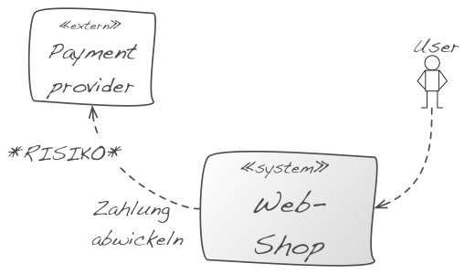
You should highlight those risks in the diagram and explain them in the accompanying text. Ideally, you refer to the risk list of your project, or rather arc42 section 11.
Further examples of risks that you should point out clearly within the context:
- Availability risk: if external systems are down: an external system heavily influences the availability of your system.
- Cost risk: the usage of an external system is expensive, individual calls or other types of use cost money. Examples are credit card checks or payment/booking services.
- Security risks: you receive/send sensible data from/to external systems. That could make these interfaces particularly interesting for a potential attacker.
- Volatility (high probability of change) of external systems: Interfaces of external systems are changed often (they are “work in progress”). The syntax and semantics of the transmitted data could be changed on short notice, which means that you either have effort adapting to these changes or you need to develop a flexible consumer for these interfaces.
- Complexity risks: using this interface is exceptionally complex or difficult, because it might have complex data structures, uses esoteric frameworks, complicated handshakes or an arbitrary mixture of those.
Tip IV-33: The context should give an overview and should not contain any details
Show Details, e.g., from external interfaces or external systems, in the block view or external interface documents.
The diagram above contains too many details of the interfaces - you could replace the seven individual interfaces to the billing component by a single “Billing” interface and show the details later in the block view.
Too many details make communication and feedback about the context boundary complicated. However, you should here at least mention domain-specific inputs/outputs and protocols.
Tip IV-34: Simplify the context boundary through categorization
Keep the context boundary simple: summarize external interfaces, systems or user roles that have strong similarities. Show explicitly that they are categories or summaries.
In diagram above, the system “Foo” sends reports to users. In the refinement of level 1 on the right you can see two different types of reports for two different groups of users. This type of refinement is desirable and consistent. The context boundary marked reports accordingly as a category. You can find such categories for many criteria (see tip below).
Tip IV-35: If many external systems are involved, merge them by explicit criteria
If your system interacts with many external systems, you can combine several of these external systems by explicit criteria. You should explicitly state these criteria. Such criteria may include:
- Systems with whom we share common or similar data
- Systems with whom we communicate within the same use case or at the same time
- Systems with whom we communicate using identical or similar technologies (e.g. categorized by ftp- and WebService)
- Systems that belong to the same or similar organization, such as: all systems of garages, insurances, glass manufacturing and tax advisors
- Systems that have similar domain or technical tasks to solve (all systems printing documents, dealing with chip cards, etc.)
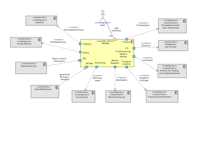
The example below marks the “Logistics” external system on the left as << category >>. On the right side, the detailed version shows three specific instances of the category << logistics >>.
Tip IV-36: Summarize “many external systems” with ports
If your system interacts with many external systems, you could use ports at the external interface of your system instead of displaying all external systems as separate icons. See below.
Das sieht auf den ersten Blick ungewöhnlich aus, kann aber Aufwand sparen. Vergleichen Sie die Diagramme aus Bild 7 und Bild 12 – es handelt sich um dasselbe System. This looks at first glance unusual, but can save effort. Compare the graphs of Figure 7 and Figure 12 - is the same system.
Tip IV-37: Show all (all!) external interfaces
We believe that aiming for completeness is usually a bad goal - with (at least) one exception: you should put all, really all, external systems surrounding your system explicitly into the context boundary. In order to save expenses, you could create categories, groups or clusters of external systems (see tip 4 34 and 4 Tip 35)
Tip IV-38: If you offer external interfaces to other systems, create discrete interface documents
The development teams building these external interfaces like compact and appropriate documentation about them. Therefore explain the usage (!) of the interfaces and not so much the fundamental concepts or justifications.
You can document REST API’s rudimentarily with tools like swagger (http://swagger.io/) or Apiary (https://apiary.io/)[^no_hypermedia_support]. Unit tests are a good choice to describe other types of external interfaces.
Tip IV-39: Differentiate domain and technical context
Especially with information systems, you can often ignore technical details of the infrastructure within the context boundary and focus on the domain related parts.
However, if hardware or technology plays an important role for your system, you need both, a domain as well as a technical context. See section 4.3.2 (Technical context).
In the figure after next below you can find a simplified example from the embedded world: the left side shows the domain context, the right side the technical context.
The figure below shows a small example of a (web-based) information system with domain and technical context.
You recognize protocols such as HTTPS or SSH within the technical context, which are intentionally not mentioned in the domain context.
Further, the (from a domain point of view external) component “Reporting” is deployed in the same technical infrastructure as the main system.
Wo ist der Hinweis zu (4 - In den Abschnitten IV.5 (Bausteinsicht) und IV.6 (Laufzeitsicht) gehen wir auf diesen Rat näher ein. Siehe Seite 30.)?
IV.3.1 Domain Context
Tip IV-40: Show rather data flows within the domain context
Apply this tip for information systems and not so much for real-time or hardware-oriented and strongly process-oriented systems. Since you are going to discuss the (domain) context boundary often with a variety of stakeholders, you cannot assume that detailed UML or modeling skills are known.
Intuitively, many people understand an arrow between software systems as data flow. (Directed) UML relationships like dependency, association, etc. are rather confusing for these individuals. Therefore: within the context, show data flows by turning around the direction of the arrow for conventional UML method or service calls.
Note: this advice is controversial in some teams, because we so explicitely do not comply with the standard UML notation, and also doing that only in the context. However, we found that data flows are often easier to communicate with (non-technical) stakeholders.
For the formalists among you: use the normal, dotted UML dependency arrow and annotate it with the stereotype << flow >> to indicate it as data flow and not as a control flow.
For less puristic UML users: invent a new arrow (e.g., solid line with arrowhead) and declare it - as suggested above - in the legend as data flow. IT veterans recognize here the the good old context diagrams from the structured analysis.
Tip IV-41: Show external influences in the context
Your system can handle different types of dependencies to external systems, e.g.:
- data or information dependencies
- temporal dependencies
- local or spatial dependencies
- hardware dependencies
- dependencies on persons, organisations or roles
- transitive (indirect) dependencies
Often you will only show user roles and data/information dependencies in the domain context. However, sometimes other types of dependencies can also be important for your system. Such dependencies can be described in the diagram itself or in an additional explanation.
An example is shown in the next figure: users must register before using the system (step 1), the system orders the text messaging (step 2), which an external text message provider sends via the mobile network (step 3). The user enters the code (step 4), and in step 5, the system verifies the identity of a person against an external branch identity server, which, in turn, triggers a verification at a registry office (step 6).
Steps 3 and 6 are transitive (also called indirect) dependencies. The system depends on the registry office, even if it doesn’t use it’s interface directly. The system is maintained by administrators, who have only access via a hardware device (Hardware Access Control, HAC). The system and the HAC must be physically in the same room - a spatial dependency. Some of these dependencies have impact on the achievement of the quality requirements for your system - and therefore can be risks (see tip IV 32).
Tip IV-42: Read Douglas Adams
We are currently at number 42: if you like science fiction, and at the same time have a quirky sense of humor … then Douglas Adams’ book “The Hitchhiker’s Guide to the Galaxy” would be a reading recommendation. After all, the number from arc42 comes from there…
Tip IV-43: Show transitive dependencies in the context
Systems have sometimes indirect (transitive) dependencies that may be relevant for communication with some stakeholders. Include those dependencies in your context. An example is shown in the figure above: The dependencies 3 and 6 as well as the registry office in the upper left corner are indirect.
Caution: transitive dependencies in the context contradict the rule of economicalness (as you get additionel elements by showing transitive dependencies). Therefore you should only describe them if it is necessary for understanding the actual situation.
Tip IV-44: Pay attention to quality requirements for interfaces
Special quality requirements may apply to interfaces of your own system and maybe as well to your external systems, e.g. safety, throughput or availability requirements. These so-called “service levels” need to be treated with care, because they may have high implementation and operating expenses and -risks.
Consider also (tip IV 32) with respect to risks of external interfaces.
IV.3.2 Technical Context
Tip IV-45: Show the technical context
You should show hardware and infrastructure of your system, such as computers, processors, networks or buses. Especially for integrated hardware/software systems (embedded systems) you almost always need a technical context. The embedded systems context diagram above (right side) is such an example. However, it may also be important for information systems to show some aspects of hardware and infrastructure already in the context, e.g. for security issues (see the webshop example above).
Tip IV-46: Use the technical context to describe protocols or channels
As you have already seen in the webshop and embedded software examples above, you can explicitly label protocols (SSH, HTTPS, VPN) or channels (CAN bus) within the context.
Tip IV-47: Explain the relationship between a functional interface and its technical realization
(wie übersetzen wir fachlich und technisch am besten?))
In case your functional interfaces are realized in the technical infrastructure through different technical channels, protocols or interfaces, you should explicitely describe the functional-technical mapping.
A simple example of such a situation can be found graphically here (Link-TODO). The relationships (mapping) can be described easily with a table:
| Function | Technical |
|---|---|
| Brake interrupt | CAN bus |
| Driver oversteer | |
| Revolutions per minute | |
| Throttle position | |
| Control value | |
| User commands | Keys in cockpit |
| Status information | Audio output |
| Display in cockpit |
Tip IV-48: Show the technical context in the deployment view
You can move technology and infrastructure into the deployment view (arc42 chapter VII) if your focus is on functional topics and abandon the technical context (arc42 chapter III-2)
But if technology and infrastructure is important to you, then you should give this overview already in the technical context.
Tip IV-49: Show variants of the technical context
If your system is used in different working or application environments, you can represent this in the technical context boundary. In the following figure you can see a system in a test environemt (left side) and in a significantly more complex production environment (right side). Alternatively, you can show such variants in the deployment view in arc42 section VII.
[^no_hypermedia_support] Silvia Schreier noted correctly that these tools unfortunately ignore hypermedia.
IV.4 Tips for solution strategy
Tip IV-50: Explain the solution strategy as compact as possible (e.g. as list of keywords)
- Explain your solution strategy in keywords, e.g. as a short list of relevant decisions or approaches.
- Explain the details as a concept in arc42 section 8 (crosscutting concepts).
You should emphasize on creating an overview, less on completeness or detailed explanations.
Tip IV-51: Describe important solution approaches as a table
Describe the solution approaches as a table containing the following columns:
- quality goal: What’s the top-level goal?
- scenario: What is a or the detailed scenario for this quality goal?
- solution approach: How does the system approach this scenario? What tactics, approaches or decisions have been taken in this direction?
- link to details: Where are the details of this solution described? This link will either point to a concrete building block, (implementing the approach) or a section of the crosscutting concepts.
| Quality goal | Scenario | Solution approach | Link to Details |
|---|---|---|---|
| <Q-goal 1> | <Text> | <Text> | <Link> |
| <Q-goal 2> | <Text> | <Text> | <Link> |
Tip IV-52: Describe solution approaches in context of quality requirements
<t.b.d.>
Tip IV-53: Refer to concepts, views or code
(instead of repeating such details in the solution strategy)
<t.b.d.>
Tip IV-54: Let the solution strategy grow iteratively / incrementally
<t.b.d.>
Tip IV-55: Justify the solution strategy
<t.b.d.>
IV.5 Tips for the building block view
Tip IV-56: Use common structures for sections of the building block view
Regardless on the level-of-detail or abstraction level you’re currently documenting or specifying: Use uniform:
- whitebox representations to (graphically) explain structures and inner workings
- blackbox representation to explain responsibiliy and interfaces of single building blocks
Whitebox descriptions
Every whitebox explains the internal structure and internal interfaces of a “higher-level blackbox”, usually by a diagram and some textual explanation.
You might use UML or any box/arrow kind of diagram.
Blackbox descriptions
Blackbox descriptions:
- explain responsibilities and interfaces of a building block,
- respect the information-hiding principle, thus avoiding disclosure of internal details
- can be either tabular or graphical
Other tips in this section refer to both black- and whiteboxes.
Tip IV-57: Organize the building block view hierarchically
Explain the structure of your source code as a hierarchy of white- and blackboxes, starting from the context view (arc42 section 3).
The context shows the complete system as a blackbox, which the building block view level-1 refines as whitebox.
The diagram below schematically shows this hierarchy:
- Level 1 is the white box description of the overall system together with black box descriptions of all contained building blocks.
- Level 2 zooms into some building blocks of level 1. Thus it contains the white box description of selected building blocks of level 1, together with black box descriptions of their internal building blocks.
- Level 3 zooms into selected building blocks of level 2, and so on.
In the diagram above, each rounded rectangle represents a single whitebox, which shall be documented by an instance of the whitebox template. You will not have the hierarchy in a single diagram in your concrete documentation!
Tip IV-58: Always describe level-1 of the building block view (“Level-1 is your friend”)
<t.b.d.>
Tip IV-59: Describe the responsibility or purpose of every (important) blackbox
Apart from an expressive or meaningful name, a brief description of its responsibility belongs to the really important aspects of the building block view.
- Names can become quite clear if they somehow refer to requirements fulfilled by the corresponding blackbox.
- Describe “what” the blackbox does or performs, avoid describing the “how”.
- Especially in lower levels of the building block hierarchy, single blackboxes fulfill part of the responsibility of some higher-level building block.
- Keep this description brief and compact, one or two sentences at most. Having too many “and” in such descriptions can be a sign of a missing abstraction.
Tip IV-60: Hide the inner workings of blackboxes
<t.b.d.>
Tip IV-61: Document blackboxes as table using the minimal blackbox template
<t.b.d.>
Tip IV-62: Document blackboxes with the extensive blackbox template
<t.b.d.>
Tip IV-63: Document blackboxes as structured text
<t.b.d.>
Tip IV-64: Justify every whitebox (blackbox decomposition)
<t.b.d.>
Tip IV-65: Document whiteboxes with the minimal whitebox template
<t.b.d.>
Tip IV-66: Document whiteboxes with the extensive blackbox template
<t.b.d.>
Tip IV-67: Use runtime views to explain or specify whiteboxes
<t.b.d.>
Tip IV-68: Use inheritance to describe similar behavior of multiple building blocks
<t.b.d.>
Tip IV-69: Use crosscutting concepts to describe or specify of multiple building blocks
<t.b.d.>
Tip IV-70: Document multiple levels of the building block view
<t.b.d.>
Tip IV-71: Keep your external interfaces in context and building block view consistent
<t.b.d.>
Tip IV-72: Explain the mapping of source code to building blocks
<t.b.d.>
Tip IV-73: Describe where to find the source code of building blocks
<t.b.d.>
Tip IV-74: Organize the mapping of source code to building blocks according to directory structure
<t.b.d.>
Tip IV-75: Organize the mapping of source code to building blocks according to the modularization of the programming language(s)
<t.b.d.>
Tip IV-76: Ensure that every piece of source code has its proper place within the building block view
<t.b.d.>
Tip IV-77: In exceptional cases, include thirt-party software (libraries, frameworks, middleware etc) in the building block view
<t.b.d.>
Tip IV-78: Frugally document internal interfaces
As external interfaces are often more important or critical than
<t.b.d.>
Tip IV-79: Document / specify interfaces with unit-tests
We hope that you would create such unit tests anyway… so re-use them as part of your documentation.
<t.b.d.>
Tip IV-80: Document / specify interfaces with runtime scenarios
see runtime-view
<t.b.d.>
Tip IV-81: Use building block view level-1 for “further” information
e.g. management information, completion status, technologies used, release/deployment information
<t.b.d.>
Tip IV-82: Refine several building blocks at once, if that’s adequate
<t.b.d.>
Tip IV-83: If you refine several building blocks at once, ensure uniqe mapping
Every blackbox in the refined whitebox shall belong to exactly ONE blackbox on the previous level.
<t.b.d.>
Tip IV-84: Refine only a few building blocks
Economicalness.
<t.b.d.>
Tip IV-85: Document concepts instead of building blocks
Might save some effort.
IV.6 Tips for the runtime view
<t.b.d.>
Tip IV-87: Limit the runtime view to very few scenarios
<t.b.d.>
Tip IV-88: Explain schematic (generic) processes in the runtime view
<t.b.d.>
Tip IV-89: Explain concrete (specific)
scenarios in the runtime view
<t.b.d.>
Tip IV-90: Use runtime scenarios primarily to detect or identify building blocks - rarely for documentation
<t.b.d.>
Tip IV-91: Use sequence diagrams to describe or specify runtime scenarios
<t.b.d.>
Tip IV-92: Document or specify parial scenarios
<t.b.d.>
Tip IV-93: Use plain activity diagrams to describe or specify runtime scenarios
<t.b.d.>
Tip IV-94: Use activity diagrams with partitions to describe or specify runtime scenarios
<t.b.d.>
Tip IV-95: Use text to describe runtime scenarios
<t.b.d.>
Tip IV-96: Mix large and small building blocks within single runtime scenarios
<t.b.d.>
IV.7 Tips for deployment view
Tip IV-97: Document or specify the technical (hardware) infrastructure
<t.b.d.>
Tip IV-98: Document and explain the infrastructure decisions
<t.b.d.>
Tip IV-99: Document or specify the various (technical) runtime or staging environments
<t.b.d.>
Tip IV-100: Show the deployment view as hierarchy
<t.b.d.>
Tip IV-101: Document or specify the mapping of building blocks to hardware
<t.b.d.>
Tip IV-102: Use UML deployment diagrams for software-hardware-mapping
<t.b.d.>
Tip IV-103: Use building blocks instead of artifacts in deployment diagrams
<t.b.d.>
Tip IV-104: Use artifacts instead of building blocks in deployment diagrams
<t.b.d.>
Tip IV-105: Use tables to document or specify software-hardware mapping
<t.b.d.>
Tip IV-106: Explain intention or relevance of infrastructure nodes
<t.b.d.>
Tip IV-107: Document or specify everything which might be neccessary for operating the system
<t.b.d.>
Tip IV-108: Leave hardware decisions to infrastructure experts
<t.b.d.>
IV.8 Tips for crosscutting concepts
Tip IV-109: Restrict documentation of concepts to the most important topics
<t.b.d.>
Tip IV-110: In concepts, explain “how it should be done”
<t.b.d.>
Tip IV-111: Keep foundations of background information to a bare minmum
<t.b.d.>
Tip IV-112: Document or specify domain or business models
<t.b.d.>
Tip IV-113: Combine domain models with the glossary
<t.b.d.>
Tip IV-114: Document or specify the domain model
<t.b.d.>
Tip IV-115: Create at least a domain data model
Yes - we know that DDD is way more than just a data model - but if you don’t get at least your data right, your system is likely to fail…
<t.b.d.>
Tip IV-116: Document concepts by showing source code
<t.b.d.>
Tip IV-117: Document crosscutting concepts with the 4-quadrant-model
<t.b.d.>
Tip IV-118: Document decisions instead of concepts
<t.b.d.>
Tip IV-119: Use stereotypes to document which concepts are applied within which building blocks.
Show in building blocks which concepts are or have to be applied.
Tip IV-120: Use the arc42 topic proposals as checklist for crosscutting concepts
<t.b.d.>
IV.9 Tips for architecture decisions
Tip IV-121: Document the criteria for important decisions
<t.b.d.>
Tip IV-122: Explain reasons for important decisions
<t.b.d.>
Tip IV-123: Document or explain decisions as mindmap
<t.b.d.>
Tip IV-124: Document or explain decisions as table
<t.b.d.>
Tip IV-125: Document or explain decisions as “Architecture Decitions Record (ADR)”
<t.b.d.>
Tip IV-126: Document or explain discarded alternatives
<t.b.d.>
Tip IV-127: Document or explain decisions informally as blog
<t.b.d.>
IV.10 Tips for quality scenarios
<t.b.d.>
Tip IV-128: Keep the introduction (arc42 section 1) brief
Move details, especially of quality requirement, to this section 10.
<t.b.d.>
Tip IV-129: Document and explain the specific quality tree
<t.b.d.>
Tip IV-130: Document the quality tree as mindmap
<t.b.d.>
Tip IV-131: Use the quality tree as checklist
<t.b.d.>
Tip IV-132: Consider usage-scenarios in the quality tree
<t.b.d.>
Tip IV-133: Consider change-scenarios in the quality tree
<t.b.d.>
Tip IV-134: Consider stress- and error scenarios in the quality tree
<t.b.d.>
Tip IV-135: Use the quality tree for systematic architecture assessment/evaluation
<t.b.d.>
IV.11 Tips for risks and technical debt
Tip IV-136: Search for risks with different stakeholders
<t.b.d.>
Tip IV-137: Examine external interfaces for risks
<t.b.d.>
Tip IV-138: Identify risks by qualitative architecture evaluation
<t.b.d.>
Tip IV-139: Examine (development/deployment/etc) processes for risks
<t.b.d.>
IV.12 Tips for the glossary
Tip IV-140: Take the glossary seriously
(DE: Nehmen Sie das Glossar ernst) <t.b.d.>
Tip IV-141: Document the glossary as a table
<t.b.d.>
Tip IV-142: Keep the glossary brief and compact
<t.b.d.>
Tip IV-143: Restrict the glossary to relevant terms, avoid trivia
<t.b.d.>
Tip IV-144: Make the product owner be responsible for the glossary
<t.b.d.>