Additional hardware
I can do quite a lot with the machines described in the previous chapter an for most projects I don’t need any further hardware. But sometimes things won’t work without additional hardware at the peripherals. This chapter will offer you a few tips.
I²C Bus
The pins of the I²2 bus are led through J8 (ALIX.3) and J13 respectively (ALIX.2, ALIX.6). I may have to solder on a pin header depending on the assembly of the board. Using this connection it is possible to attach further circuits which are accessible by the I²C bus. I²C tools (software package i2c-tools from Debian) helps to setup these circuits. If necessary I can look up in the kernel documentation to find out which sensors are already supported by the kernel.
The kernel’s interface is one simple way to work with the I²C bus. I access this interface by loading the kernel module i2c-dev.
# modprobe i2c-dev
After loading the module, a device file is often automatically created under /dev/ for each I²C bus of the machine. On ALIX boards /dev/i2c-0, this is only done for the first and only bus. If the device file isn’t created automatically I can do this manually using the command mknod:
# mknod /dev/i2c-0 c 89 0
With the command i2cdetect I can verify whether a circuit has been detected on the I²C bus. A PCF8591, with all address bits set to 0 should appear at address 48 hex:
# i2cdetect -y 0
     0  1  2  3  4  5  6  7  8  9  a  b  c  d  e  f
00:          -- -- -- -- -- -- -- -- -- -- -- -- --
10: -- -- -- -- -- -- -- -- -- -- -- -- -- -- -- --
...
40: -- -- -- -- -- -- -- -- 48 -- -- -- 4c -- -- --
...
I use the programs i2cset and i2cget to send and read data via the I²C Bus. This allows me, for example, to query the values at the four analog inputs of a PCF8591as follows:
# i2cget 0 0x48 0x40
0x80
# i2cget 0 0x48 0x41
0xff
# i2cget 0 0x48 0x42
0x20
# i2cget 0 0x48 0x43
0x00
# i2cget 0 0x48 0x40
0x73
With this circuit I need to remember that it provides the value for the control word (0x40..0x43) of the previous query in the next query. You will find more information about this in the circuit’s datasheet; the corresponding manual pages will help you with the programs.
Serial Interface
With a little bit of soldering I may be able to use an additional serial port directly on the board. The ALIX 2D13 model has a second serial interface at connector J12 with a 3.3V CMOS signal level which I can convert with the right converter.
If I don’t want to get my hands dirty or don’t want to burn my fingers (for lack of soldering skills) I can always use USB-to-serial converters. Here the problem sometimes arises that the converter gets reset when connecting or disconnecting the serial interface and a new name is given by the kernel (for instance ttyUSB1 instead of ttyUSB0). Thus programs which use the serial interface may get mixed up. I have to use appropriate udev rules to counteract this.
Sound cards
Here I can use USB sound cards. According to their homepage, any sound devices that support a standard USB Audio Class 2.0 (UAC2) interface will work with Voyage Linux MPD. Alternatively I may use the onboard audio device that comes with the ALIX.1d or ALIX.3d3 devices.
UPS
Willy Tarreau wrote a web article about how to build a cheap UPS with very few components that could sustain an ALIX computer for about ten minutes. That’s not a lot of time to save the world but at my home the power fails a few times a year long enough to shut off all computers without UPS or battery (notebooks). And for those short blackouts 10 minutes are more than enough. You can also use it to plug the power supply into another socket without having to restart the system.
There is just one small problem with this UPS: after these ten minutes the power fails just as it would have done without the UPS. So if I want to use the time gained by the UPS for something important, such as saving some important files from memory to disk, the system has to know when it is running on battery.
Fortunately with a few resistors and a PCF8591 circuit I can augment the circuit so that the system can query the state of the power supply via I²C bus and - after some test runs - make some predictions about the remaining battery time. This makes this cheap UPS suitable for a broader scope of applications.
The circuit
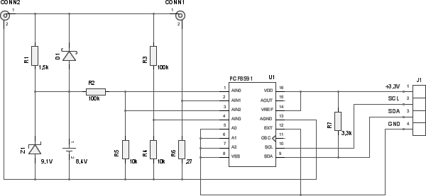
USV with monitoring extension
Willy Tarreau’s original circuit consists of a rechargeable 8.4V battery, a current-limiting resistor R1, a Zener diode Z1, which limits the charging voltage for the battery and a low voltage Schottky diode D1 which conducts the current from the battery to the ALIX board if there is a power outage.
The extension that makes it possible to query the state of the UPS consists of voltage dividers R5/R2 and R4/R3 as well as a resistor R6 which works as a measuring current transformer. These prepare the voltage level and the total current in such a way that they can be processed at the analog inputs of the PCF8591. Resistor R7 pulls the I²C data bus (line SDA) to VCC because the output lines of the circuit only pull it to GND.
Notes on dimensions
R1 limits the charging current for the battery. The 18V from the power supply unit reduced by 8.4V nominal voltage from the battery makes about 9.6V. Willy Tarreau recommends values between 820 and 1500 ohms. This would make the charging current 12 to 6 mA. If there is a short in the battery poles an 820 ohm resistor must dissipate about 400 mW. With 1500 ohms it is still 220 mW and the resistor must sustain this dissipation loss.
The Zener diode Z1 takes the charging current once the voltage of the battery reaches the avalanche voltage. Willy Tarreau specified a voltage of 9.6V in his circuit. I had only 9.1V diodes at my disposal. The voltage can be expanded with an additional diode connected in series. With 820 ohms for R1, the current through Z1 is about 10 mA which leads to about 100 mW of heat that has to be dissipated. With 1500 ohms for R1 it is less than 65 mW.
The Schottky diode has to continuously support the full current of the ALIX board should power fail. According to the specification, peak power is 6 watts and the device runs on at least 7 volt. That means this diode has to support at least 1A of continuous current.
According to Willy Tarreau’s article, an 8.4V battery keeps the ALIX board online for about 10 minutes until the voltage drops below 7 volts. Around 24 hours are required for a complete charge with a 1500 ohm resistor.
To dimension the monitoring circuit with the PCF8591 I will briefly touch upon the wiring. The A/D converters compare the analog input voltage with the voltage reference (VREF) in 256 steps (8 bit). Accordingly they should not be above the voltage reference (VREF) and not below the analog ground (AGND).
VREF comes from the I²C port of the ALIX board and is 3.3V with reference to the VSS. The VSS is the ground wire of the ALIX board at the hot end of R6. This means that the analog voltage reference is 3.3V plus the potential difference in R6 (it floats a bit depending on the current taken by the ALIX board). With a minimum voltage of 7 volts and 6 watt power loss, the maximum current through R6 is less than 1 ampere.
To keep the potential difference in R6 low, I chose 0.27 ohms for this resistor. Thus the maximum difference is less than 0.3 volts and the voltage reference for the A/D converters is between 3.3 and 3.6 volts. This voltage, divided by 256, gives a precision in the A/D converters of between 13 and 14 mV per digit. This equates to a current of 48 to 52 mA per digit on the 0.27 ohm resistor. This is the precision with which I can estimate the voltage and the current.
With a total of one ampere I can use a resistor with a maximum thermal dissipation of half a watt.
Because the input voltage from the power supply is a maximum of 20 volt and the voltage reference is between 3.3 and 3.6 volt, the ratio of R5 to R2 and R4 to R3 should not exceed one sixth. I am on the safe side with a ratio of 1 to 10. Using the precision of the voltage reference I can estimate that the power input and the battery power is 0.13 to 0.14 volts per digit.
Querying the state of the UPS
I use the analog inputs AIN0 and AIN1 in the circuit to query the absolute values of the battery voltage and the total current. The inputs AIN2 and AIN3 are queried as a difference value. This way I only need to observe the polarity of this value to know whether the board is running on battery or power supply.
The way the inputs are connected, I obtain with the control bytes
- 0x60 the battery voltage
- 0x61 the total current
- 0x62 the polarity and the voltage in R1 and D1. Here the most significant bit (MSB) is enough to determine if the board is running on battery or not.
Alternatively I can obtain with the control bytes
- 0x40 or 0x42 the battery voltage
- 0x41 the total current
- 0x43 the output voltage, that is fed into the ALIX board.
Then I have to subtract the battery voltage from the output voltage to determine whether it is running on battery or not. Because I need two query cycles it is better to first query the battery voltage. (If the power fails between these two queries, the battery voltage would still appear to be less than the output voltage and that would mean the board is fueled by the power grid).
I made a test set-up with a power supply of 12 volts and obtained the following readings.
# i2cget -y 0 0x48 0x60
0x80

# i2cget -y 0 0x48 0x61
0x3e
# i2cget -y 0 0x48 0x62
0x07
# i2cget -y 0 0x48 0x60
0xdc
And with the power supply switched off:
# i2cget -y 0 0x48 0x61
0x3d
# i2cget -y 0 0x48 0x62
0x0c
# i2cget -y 0 0x48 0x60
0x01
Here the third value stands out because its sign changes (negative when on power supply, positive when on battery) and because its absolute value changes (charging voltage difference in R1 versus flux voltage of D1). Furthermore the current drain is higher when the battery in order to compensate for the lower voltage.