Tool Setup
In this chapter we will prepare your development environment by installing all the tools necessary. Drivers are needed to communicate with the ESP8266, a tool called “Arduino IDE” will let us write code, and a sample project will prove that the components are working well together.

Download and Install the Serial Driver
To program the NodeMCU V1.0, your development platform (PC, Mac, Linux) needs to detect the Serial-To-USB adapter soldered onto the ESP8266 module. There are two different versions: some have the CP2102 Serial-To-USB adapter; others have the CH340. My guess is that most new modules come with the CH340 chip.
If your module has the CP2102 converter then you can download and install the driver from here: https://www.silabs.com/products/mcu/Pages/USBtoUARTBridgeVCPDrivers.aspx
In case your module comes with a CH340 serial-to-USB converter then download the drivers from here:
- Win: http://blog.squix.org/downloads/CH341SER.zip
- Mac: https://blog.squix.org/wp-content/uploads/2016/12/CH34x_Install_V1.3.zip
The Arduino IDE
The Arduino Integrated Development Environment (IDE) is the tool you will use to program the ESP8266. IDEs are more than just editors; they help you with various tasks during the development process. For me as a professional software developer the Arduino IDE is not a very powerful one. It lacks some features that I got used to and I am missing them every time I program for the ESP8266. But the Arduino IDE was not made for professional programmers, it was made with the beginner in mind and this is also the reason why we will use it here. If you are looking for more convenience, have a look at http://platformio.org/ or the ESP8266 integration into the Eclipse IDE.
To install the Arduino IDE go to https://www.arduino.cc/en/Main/Software and download the latest version matching your operating system:
- For Mac OS X you can download a ZIP file which you then have to extract. Take the extracted application “Arduino” and move it to your Applications folder.
- For Windows you have the option between an executable installer and a ZIP file. The ZIP file might be the better option if you do not have administrator permissions on your system. The installer on the other hand can put the libraries in the proper places.
Now you have a bare Arduino IDE which brings everything needed to write programs for the standard Arduino ATmega chips. But we want to write and compile code for the ESP8266, right?
Install the ESP8266 tool chain
A tool chain is the set of tools that lets you compile and create binaries for a certain platform. Since we want to create binaries for the ESP8266 we need a different tool chain than the one that comes with the plain vanilla Arduino IDE. To save you the hassle of downloading many different files and copying them into obscure locations, the Arduino IDE has a wonderful feature: the Board Manager. It lets you install support for many different chips and boards with just a few clicks. But first of all we have to tell the Arduino IDE where it should look for board definitions:
Open the Arduino IDE
- Go to your preferences/settings and in the text box
Additional Board Manager URLsenter this URL: http://arduino.esp8266.com/stable/package_esp8266com_index.json - Now go to
Tools > Board: … > Boards Manager…, search for the ESP8266 board and clickInstall. - Get a coffee and wait until it finishes.
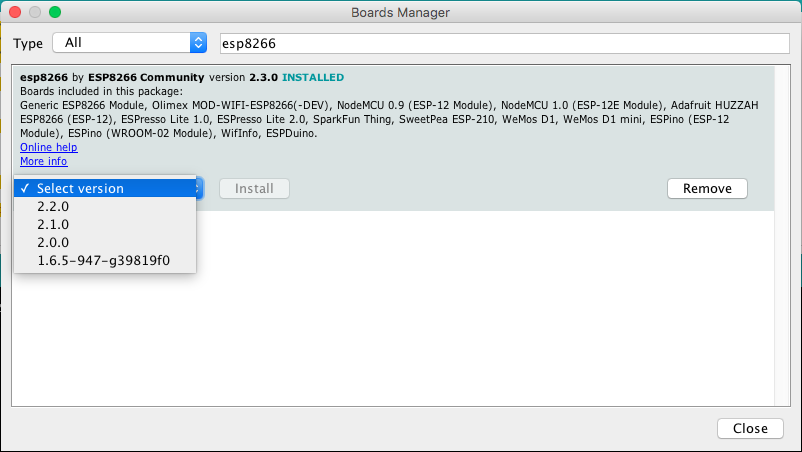
From time to time you want to come back to the Board Manager and make sure that you have the latest version of the ESP8266 tool chain installed. To do that simply click on the ESP8266 entry and select the latest version from the dropdown. Then click Update.
Selecting the Correct Board
Now your Arduino IDE knows about ESP8266 boards in general. But not all the ESP8266 boards are the same; there are subtle but important differences in available Flash Memory and how they can be programmed. The selection of the correct board also defines the names of the GPIO pins: the designers of the NodeMCU decided to introduce a completely new naming scheme for the pins. Instead of calling them GPIO1, GPIO2 etc they decided to give them different numbers by using a “D”-prefix. So D0 is GPIO16, D1 is GPIO5 and so on. By selecting a NodeMCU board you automatically have the D naming scheme available, and this helps a lot since these names are also printed on the module board.
So let’s pick the correct board. If you bought the original Squix Starter Kit you will have to choose a NodeMCU 1.0: Go to Tools > Board: * > NodeMCU 1.0 (ESP-12E Module)
There is a plentitude of modules available. Please make sure that you have the correct board selected before you continue.
Setting the Correct Port
In an earlier step you already installed the drivers for this converter. If everything went well and the board is plugged into your computer you should now be able to select the serial connection. It should show up in the Menu under Tools > Port. On my Mac the device is called /dev/cu.SLAB_USBtoUART. On a PC it should be listed as a COM port labelled COM# (where # is some number).
If you cannot see a device that looks like the NodeMCU, try to unplug the ESP module and re-plug it after a few seconds. Also try a different USB socket. If that doesn’t help consider restarting your computer… Make sure that you installed the driver as mentioned in the chapter about drivers.
Testing the Setup: WiFi Scanner
Thanks for bearing with me until we get to the really cool part. We are going to run our first program on the NodeMCU! In the Menu of the Arduino IDE go to
File > Examples > ESP8266Wifi and select WiFiScan.
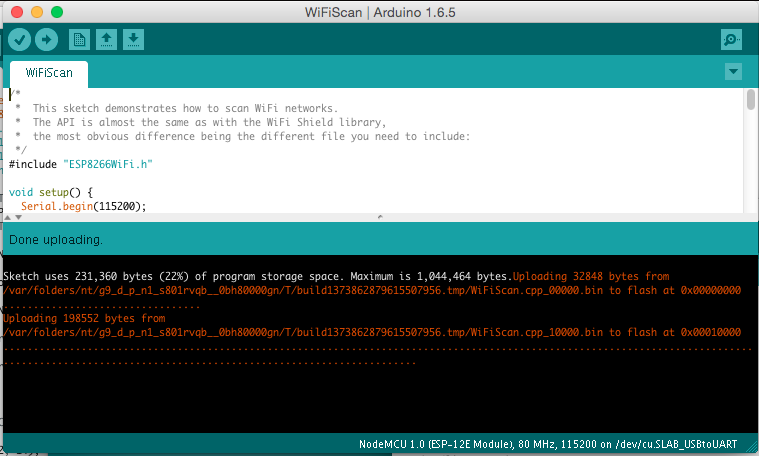
A new window will open up. This window is your current project and is also called a “Sketch”. To compile and transfer the binary to the ESP8266 click on the green circle that contains an arrow on the very top of the window. If everything went well this will compile the sketch and upload the binary to the ESP. It might look something like this:
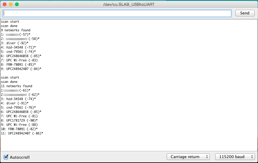
If you see Done uploading. in the window, then click on the magnifying glass on the top right of the window. This is the serial console that you can use to see output from the NodeMCU module, or to send commands to the device. Make sure that the baud rate is set to 115200. This rate is also set in the example code, and if you have a different setting the ESP will talk with a different speed than your PC listens. You can set the baud rate on the bottom left of the serial monitor. My output looks like this:
If you see something similar: congratulations! You have just set all the preconditions to run the WeatherStation code.
Trouble Shooting
Let me be honest: there are many reasons why this setup might not work. But don’t give up so quickly! With a careful and analytical approach we will manage to get the ESP8266 running! The following paragraphs are structured by symptom and I will give you some ideas how to find the problem and how to solve it.
No serial port shows up after you connect the ESP8266 to your computer
This is a tough one because this is a symptom for many different causes:
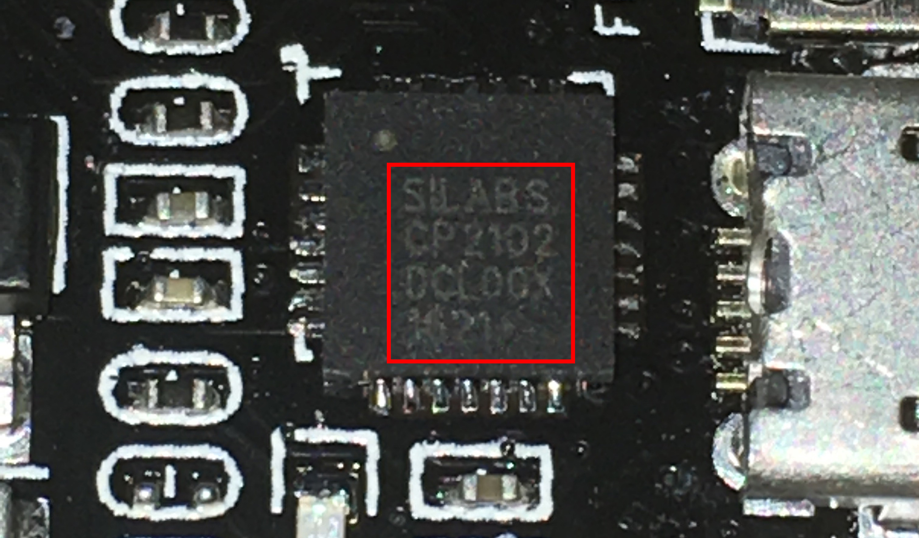
- First please make sure that you have installed the correct driver, either for the CP2102 or the CH340. If you are not sure which one your ESP8266 has then better install both. The extra driver will only be used if you attach a matching hardware. The photo below shows how the CP2102 from Silabs looks like.
- Another possible and frequent culprit is the USB cable. If you are sure that you installed the right drivers then try to use a different USB cable with the ESP8266. As a cross check you can also use the USB cable with another device (e.g. smartphone) and connect it to your PC. If the device is not recognized by your computer (and it is one that should be recognized) then throw the faulty cable away
- Sometimes it helps to restart your computer or choose another USB port. It happened to me several times that one USB port stopped working and only after a restart or changing the port the device would show up.
- It also happens relatively often that the NodeMCU is dead. But it is relatively hard to be 100% sure that it is really not working. If you previously didn’t identify driver or cable as the cause for the problem we should focus on the NodeMCU module. Let’s have a close look at the device. There are two LEDs: one on the ESP8266 module close to the antenna and the other one closer to the buttons. Do you see anything blink when you plug in the USB cable and connect it to your PC? If it blinks then the ESP8266 could be OK but the Serial-to-USB converter could be damaged. If there is no light then there are still many possibilities.
Failure during upload like espcomm_upload_mem failed
When you try to upload you see something like this in the console:
1   warning: espcomm_sync failed
2   error: espcomm_open failed
3   error: espcomm_upload_mem failed
4   error: espcomm_upload_mem failed
This means that for a number of reasons your computer could not upload the firmware to the NodeMCU. To understand what might be
the cause we need to see what is happening during the upload of a new binary. Before the availability of easy-to-use developer modules
like the NodeMCU you had to manually connect some pins of the ESP8266 to boot it into flash mode after a reset. This was very annoying
since for every change in the code you had to compile, connect the pins, reset the ESP, wait until upload was complete, disconnect the
boot mode pins and do a reset. Modules like the NodeMCU make this a lot easier since they have a special circuit which does all that
when the serial-to-usb converter detects a special signal from your computer. Wonderful, right? Except: it doesn’t always work.
First let’s try if the serial connection is working at all. Connect the NodeMCU to your computer and open the serial console.
Now press the RST button and check what will be printed in the console. Depending on the selected transfer speed
(lower right corner of the serial monitor) you either see strange characters or something similar to this:
1 ets Jan  8 2013,rst cause:2, boot mode:(3,6)
2
3 load 0x4010f000, len 1384, room 16
4 tail 8
5 chksum 0x2d
6 csum 0x2d
7 v3ffe85e8
8 ~ld
I had to set the speed to 74880 baud to get this output. If you see this text then your computer and your ESP8266 can communicate with each other. Now we try to fix it by one of these measures:
- Press and hold the button labelled
FLASHwhile pressing the button labelledRST. Then try again if the upload works. This button combination will manually set the ESP8266 into flash mode - The settings in the Arduino Tool menu are also a frequent source of problems: have you selected the right board (e.g. NodeMCU V1.0) and the right USB/Serial port? Try also different upload speeds. The NodeMCU should automatically detect the requested transfer speed but this does not always work.
Summary
Before we continue to the WeatherStation project let’s have a closer look at what we just accomplished:
- We installed a driver which lets us program the ESP8266 with custom code that we wrote. Which driver needs to be installed depends on the Serial-to-USB converter we use. Some ESP modules already have such a converter; others will need an additional one.
- We downloaded and installed the Arduino IDE. In the IDE we write the code, compile it and transfer it to the embedded device. If our code supports it we can even use the Serial Monitor to communicate with the device.
- We used an example project, called a Sketch, to test our setup. The sample project installs firmware which uses the WiFi module to scan for available WiFi access points. It repeatedly writes this data to the serial line, and we can display it by opening the Serial Monitor tool. Remember, in a serial communication both parties need to agree on the speed the characters are getting transmitted. The example sets this to 115200 baud.