1. OSPF Basics
1.1 Evolution
OSPFv1 was first standardized with RFC 1131 in October 1989. In July 1991 the first attempt to standardize OSPFv2 was made with RFC 1247, followed by RFC 1583 (March 1994), then by RFC 2178 (July 1997), and finally by the current Internet Standard, RFC 2328 (April 1998). Below, you can see the timeline with several important RFCs over OSPF’s lifetime:

The key takeaway from the above time-line is that OSPF is the evolution of a 30-year old protocol (OSPFv1), and has at this time already been a standard for over 20 years. Maybe not as old as BGP or DNS, OSPFv2 is an old protocol. You must keep in mind that no single IGP will be able to cover all of today’s network’s requirements, nor was any currently available IGP designed with today’s actual requirements in mind. Being one such example, OSPFv2 is not the perfect routing protocol for every network deployed today. The fact that noone could anticipate today’s needs, scale, and demands, only serves as a testament that a protocol that was designed more than 20 years before these networks were even conceived or deployed and is still holding its ground, is a protocol well designed. In reality, there is no consensus among the most prominent network engineers as to which IGP is the best for particular corner cases, let alone a blanket endorsement. So the next time you are frustrated with a feature (or lack thereof) in OSPF, try to remember the history of OSPF, what it was designed to solve initially, and all the trade-offs the designers were called to make without having the benefit of hindsight. The appreciation of OSPF’s history and the monumental effort put in by its creators ought to initially diffuse any frustration about its efficacy, and in turn create in its place amazement at how our Internet is actually even holding together, so many years after the original assumption of technical debt.
1.2 Principles of operation
OSPF is a Link State routing protocol. The protocol’s end goal is to populate a router’s routing table with destination prefixes and next hop information for every such prefix. Furthermore, this information has to (most of the time) meet some quality criteria such as:
- The information has to be valid, ie next hop should really exist and the prefix should truly be reachable via the next hop.
- The information should be such that a routing loop will not be established in the network.
- The information should be optimal (ie the next hop should be the best of any possible next hops, based on a predetermined best path criteria).
- If multiple paths exist toward a destination of equal preference, add several next hops to the routing table.
The above list is by no means exhaustive. The manner by which routing protocols provide this information to a router can be distinguished in the following three:
- Distance Vector
- Link State
- Vector Path
There are other ways by which a routing table can be built besides by using a classical routing protocol. Static routes are one simple and non-scalable manner and SDN is another up and coming way. This book will focus on a rather classical Link State routing protocol, OSPF.
A Link State protocol behaves akin to a distributed eventually-consistent data store, where the data maintained in the datastore is data about the state of the links and routers across the network. Once all this data is disseminated to all OSPF routers, each local OSPF process processes the data and derives routing information, which the OSPF process feeds to the router’s global Routing Information Base (RIB).
OSPF functions can broadly be divided into the following:
- Build and maintain the distributed datastore.
- Use the data in the datastore to build a routing table locally.
The datastore in OSPF is called the Link State Database (LSDB). The individual pieces of data in the LSDB are called Link State Advertisement (LSA). Each OSPF router originates several LSAs which then feed into the LSDB. No single entity is responsible for verifying that all OSPF routers in an OSPF routing domain have the same LSAs, or that the latest LSA has been disseminated to all routers. The distribution of LSAs and the synchronization of the LSDB is a decentralized function.
At a minimum, every router will originate a single LSA describing itself and any OSPF neighbors it may have discovered. The same LSA that describes the router (the Router LSA as it is aptly named) also describes any stub networks attached to the router. Such stub networks are directly connected networks over which there is no OSPF neighborship.
Beyond the minimally mandated Router LSA, a router may originate a number of different LSAs, each describing a different aspect of the OSPF network, and beyond.
To synchronize the LSDB, OSPF routers setup neighborships with neighboring OSPF routers. These neighborships allow each OSPF router to keep track of any neighbor’s availability, basic configuration, and LSDB state. The OSPF protocol dictates that every OSPF router must inform all of its neighbors whenever it receives a new LSA. If any neighbor does not acknowledge that it has received the latest update to the LSDB (a new LSA) the OSPF neighbor has to tear down the neighbosrship, or risk have an inconsistent LSDB throughout the OSPF routing domain.
After the OSPF router synchronizes its LSDB with all its neighbors, it uses the SPF algorithm to extract routing information from the data in the LSDB.
The purpose of the SPF algorithm is to find the shortest path to each node within an area. In the OSPF graph, routers and networks are nodes (vertices), while links are always represented as edges. OSPF builds a directed graph describing the network at large, and then runs the SPF algorithm to determine the best path between any two nodes.
Network nodes are IP subnets attached to at least one other router node.
OSPF builds a graph describing the actual physical network. A graph is a mathematical model of a network, and in OSPF it only exists in the router’s memory as a data structure. A graph consists of nodes and links. OSPF uses nodes to describe the following objects:
- Routers
- Transit networks
- Destination networks
Destination network nodes are also called stub network nodes.
In reality, a multi-access segment over which two OSPF routers establish an adjacency is modeled as both a transit network and as a destination network. This translates into the following:
- If you need to find the path between two routers on the common segment you have to go through the transit network node.
- If you need to reach a destination attached to the multi-access segment, you need to route to the destination network. It just so happens though that the destination network node is attached to the transit network node.
OSPF optimizes its operation by not extending the SPF to each stub network node. Instead, OSPF only builds a shortest-path tree from the current node (OSPF only runs on router nodes) to each router node and transit network nodes. After the Shortest Path Tree (SPT) is built, OSPF cross-references the attached stub networks with each of the nodes in the SPT, and thus determines the shortest path to each IP subnet.
To clarify how such an optimization works, we now need to differentiate between transit networks and stub networks. Each type of network gets its own node in the OSPF area graph. Transit networks are by definition networks between two or more router nodes and are used for traffic that is transiting between two of those attached routers. Stub networks are networks attached to routers but cannot be used to carry transit traffic.
RFC 2328 considers stub networks, that are connected to OSPF routers, as nodes as well. For example, consider the following network:

Assuming that R2 and R3 do not form an adjacency over the 10.1.0.0/24 network, the OSPF graph will look like the following:
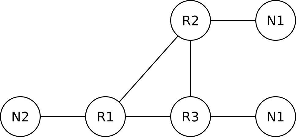
The goal of OSPF is to find the shortest path from a router (say R1) to a destination network (N1 for example). Assuming all links in the above network have an equal cost, R1 will load balance between R2 and R3. Strictly speaking, R1 is routing to reach node N1, but for the purposes of this chapter we will ignore the network nodes and only consider routers as nodes, and any attached networks as properties of these nodes. So, from now on, the OSPF graph of our small network will look like the following:
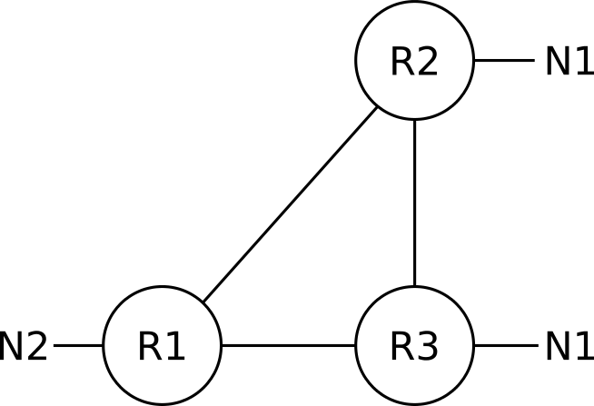
Transit networks (networks over which two or more OSPF routers establish an adjacency) are still represented as nodes in the OSPF graph, despite the above simplification.
While trying to not get bogged down in details in this first chapter, keep in mind that the above representation is a simplified version of the various nodes that would be used to describe the example network in OSPF. In reality, the IPv4 networks (subnets) that are configured between routers R1, R2, and R3 will be modeled in OSPF either as stub networks attached to both ends of a link (like N1 is attached to both R2 and R3), or as a separate transit network node; unless prefix suppression is configured on the involved routers.
1.3 The LSDB
The LSDB as OSPF’s data store shouldn’t be thought of as a local database of LSAs but rather as a global database. The process that builds and maintains the database is quite independent from the process that reads the database and uses the LSDB’s data and writes changes to local conditions to the LSDB. The figure below shows a conceptual view of how a local OSPF process sees the LSDB.
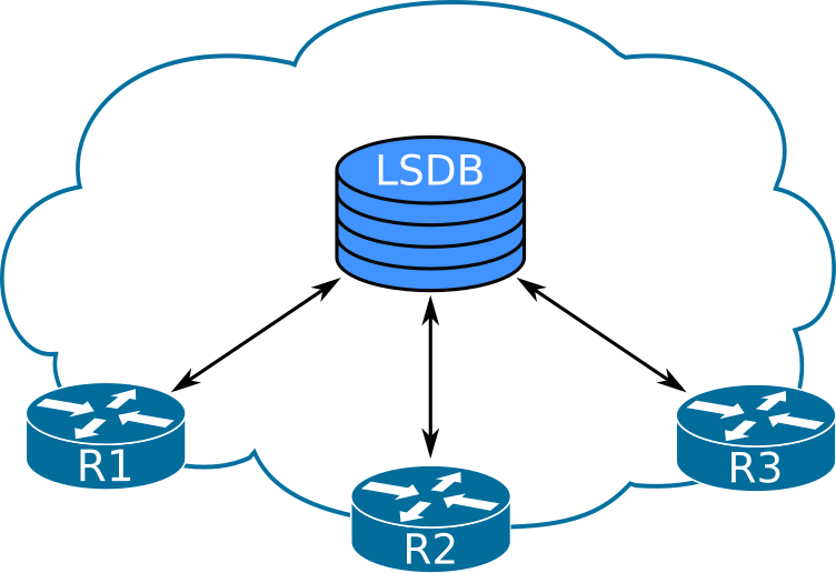
The fact that the LSDB is read from the router’s local memory (instead of from somewhere else) is simply a design choice of OSPF designers. They could just as well have put the LSDB to a central location, and the functionality and behavior of OSPF would have been the same. Actually, a central database would allow for the database to be way more consistent than the OSPF LSDB ever is. The designers of OSPF sacrificed consistency to guarantee availability, since a remote centralized data store cannot guarantee availability at all times, just like how a local copy of the LSDB cannot guarantee consistency all the time.
Like mentioned in the earlier section, the LSDB stores topology and network reachability information. This differentiation of data stored in the LSDB is depicted in the following diagram.
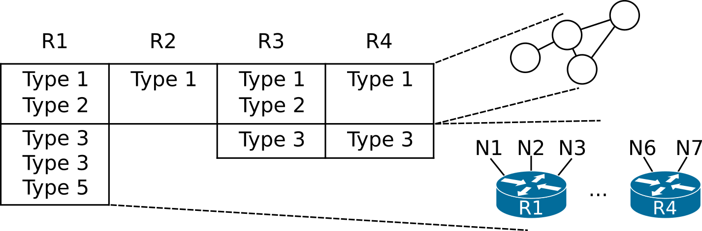
The table above represents an area’s LSDB and the columns represent the set of LSAs generated by each router. For example, R2 only originates one type 1 LSA, whereas R1 originates type 1, 2, 3, and 5 LSAs.
The type 1 and type 2 LSAs describe the network topology as a set of interconnected routers and their links. Some information in type 1 LSAs and the information stored in other LSAs describes each router’s ability to reach specific destinations.
You can compare the LSDB to another well known distributed datastore, DNS. The model in DNS is that a remote DNS server stores the data and whenever a process needs to pull a record from the database, it contacts the remote server over an unreliable network to retrieve it. This way, DNS is largely consistent but not at all times available.
The LSDB describes portions of the OSPF network called areas. It is possible to have several areas in a large OSPF internetwork, meaning that there will be several distinct LSDBs overall.
Like mentioned above, type 1 and type 2 LSAs describe the topology of routers within an area, whereas other LSAs describe various destinations that area border routers can reach. To illustrate this, consider the following OSPF internetwork:
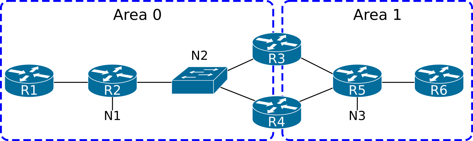
The LSDB of area 0 will only contain LSAs describing the area 0 topology and the destinations reachable through R3 and R4. In this section, we will ignore routers connected to an external domain.
The LSDB for area 0 will describe the following graph:
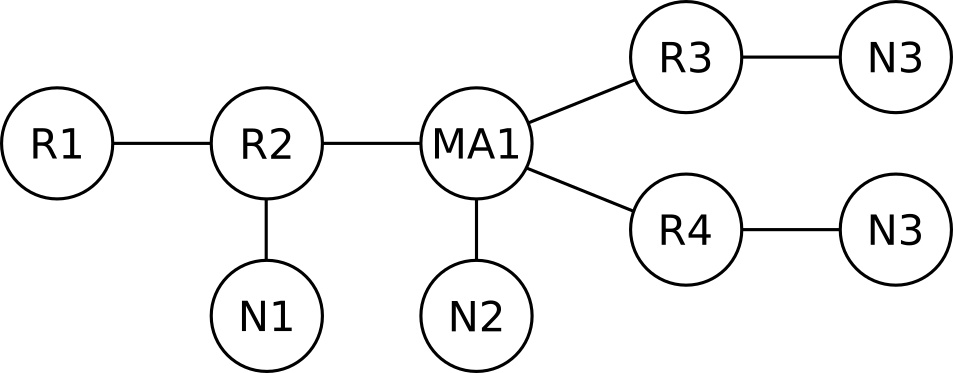
As we can see in the graph above, the border routers (R3 and R4) abstract away (hide) information about other areas.
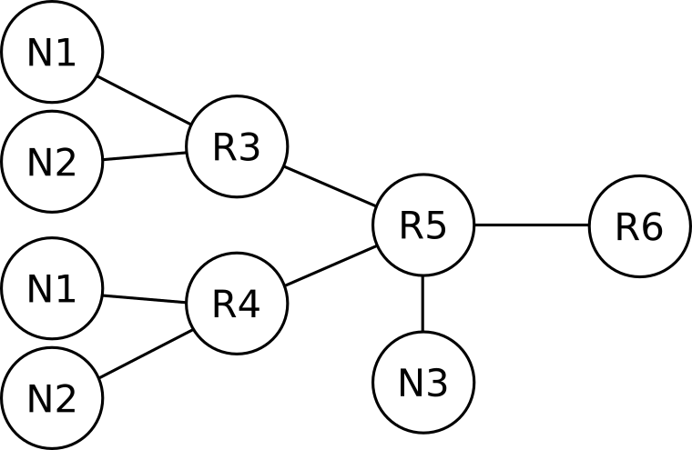
And for the sake of completeness, the LSDB for area 1 will describe the following graph, again, abstracting details from area 0.
1.4 OSPF messages
OSPF uses constructs called messages, which are directly equivalent to IP packets. Each OSPFv2 message is carried within a single IP packet, so the phrase OSPF message is synonymous to, and interchangeable with, OSPFv2 packet. RFC 2328 defines the following OSPF messages:
- Hello
- Database Descriptors (DD)
- Link State Request
- Link State Update
- Link State Acknowledgment
Each message is encapsulated within an IP packet with IP protocol number of 89 and has a 24-byte-long OSPF header. Following the OSPF header, each message’s body is different.

Upon reception of an IPv4 packet destined to the OSPF process, IOS checks the following fields to determine if the IP packet should be passed to the OSPF process (as defined in RFC 2328, section 8.2):
- The IP checksum must be correct.
- The packet’s IP destination address must be the IP address of the receiving interface or an OSPF multicast address to which the interface is subscribed. If the destination address is the AllDRouters mulicast address (224.0.0.5), only accept the packet if the receiving interface is in the DR or Backup state.
- The IP protocol must be 89.
- The source address must not be a local IP address. This check verifies that the local OSPF process does not receive back a packet itself has originated.
If any of the above check fails, IOS does not pass the IP packet’s contents to the OSPF process.
The OSPF packet header
Every one of the five OSPF messages introduced above always consists of two parts: The OSPF packet header, and the message body.
The OSPFv2 packet header functions as a very basic header, as found in most other protocols. Its main functions include:
- Describe the OSPF message at a high level
- Protect the packet with a checksum and authentication data
- Describe the sender
The format of the OSPFv2 packet header is shown below:

The OSPF packet header and its fields are described in Appendix A, section A.3.1 of RFC 2328.
The version field only takes a value of 2 or 3, for OSPFv2 and OSPFv3 respectively. The packet type field identifies which one of the five packet types the payload is. The packet length defines which part of the payload is actually protected by the checksum and authentication data, and is in bytes.
The checksum calculation algorithm is the same as the one used for the IPv4 header checksum. The IPv4 checksum algorithm has purposefully been designed to be fast, and most importantly simple to implement in hardware. The packet checksum’s design goal was to catch single-bit errors, which is typical of errors caused during transmission. The packet header’s checksum simplicity might seem like the reason why a second per-LSA checksum was added. Granted, the LSA header’s checksum uses the Fletcher algorithm and is more robust than the IP checksum, but the reason for the LSA header’s strong checksum was the in-memory corruption possibility, not the in-flight corruption.
The authentication types and data fields are discussed in the OSPF Security chapter (coming soon).
Upon reception of an OSPF message, the OSPF process first verifies the OSPF header before processing the encapsulated message. The checks performed on the OSPF header are described in section 8.2 of RFC 2328:
- Version must be 2
- The area ID must be either the area associated with the receiving interface, or area 0.
- In case the area is the same as the receiving interface’s area and the interface does not have a point-to-point network type, additionally verify that the sender’s IP address is on the same subnet as the receiving interface.
- In case the OSPF header’s Area ID is different than the receiving interface’s area, then the only acceptable OSPF message would be a virtual link OSPF message. In this case, check the following three items: The receiving router must be an ABR, the Router ID in the OSPF header must be the Router ID of a configured virtual link neighbor, and the receiving interface’s area must be a Transit area.
- The Authentication type must be the same as the authentication of the receiving interface. In case of configured authentication, the authentication checks must also pass.
If any of the above checks fail, the OSPF message is discarded. Else, the message is processed.
Apart from the checks listed above, checking the Router ID and the checksum in the OSPF header is not explicitly stated in RFC 2328, but IOS performs both of these checks.
The Router ID is verified during reception of an OSPF header to be different than the local router’s Router ID. Cisco IOS discards any OSPF messages that have the same Router ID in their OSPF header as the local router.
The OSPF header checksum is also calculated upon reception to catch any transmission errors that the IP checksum did not catch.
The structure and use of OSPF messages will be discussed in the upcoming sections.
The OSPF Hello packet
The OSPF Hello packet is used by OSPF for four purposes:
- To automatically discover directly connected, compatibly configured neighbors
- For each one of the several neighbors, verify that there is bidirectional visibility per neighbor
- As a mechanism to detect loss of connectivity from/to a neighbor
- To facilitate the establishment of adjacencies
The format of the Hello packet is shown below:

Once a Hello packet is successfully received on an interface, it is examined to verify that the sending router’s configuration is compatible with the recipient’s configuration.
RFC 2328, section 10.5, explains the detailed processing of a received Hello packet. After checking the validity of the packet’s two headers (the IPv4 and OSPF headers, as described in the two previous sections), the OSPF process verifies that three fields in the received Hello message match the configured values on the receiving interface. The three fields are:
- Subnet Mask
- Hello Interval
- Dead Interval
Any mismatch of the received values with the configured values is sufficient cause for dropping the packet, except in point-to-point links or virtual links, where the subnet mask field need not match. The following excerpt is taken from RFC 2328:
However, there is one exception to the above rule: on point-to-point networks and on virtual links, the Network Mask in the received Hello Packet should be ignored.
Cisco IOS does not verify the subnet mask on IP numbered point-to-point interfaces, nor on IP unnumbered interfaces. This is in compliance with RFC 2328. The rationale for the exception of this verification, is that unnumbered point-to-point links typically do not have an IP network number, and that the interfaces on each side may possibly not even have an IP address assigned.
From RFC 2328, section 9 (and section C.3):
On point-to-point networks and virtual links, the IP interface mask is not defined. On these networks, the link itself is not assigned an IP network number, and so the addresses of each side of the link are assigned independently, if they are assigned at all.
The only configuration that is necessary to turn an interface into a point-to-point interface is the following:
After the above configuration is applied, the subnet mask is no longer checked on the interface; only that the neighbor’s IP address is reachable. This behavior has been verified with IOU 15.4(2)T.
A deep dive into network types and their default settings per interface type can be found in the Network Types chapter.
The list of neighbors contains the Router IDs of any neighbor the router heard of on the current segment, not all the neighbors (on any other segment the router is attached to).
Unicast vs. Multicast Hellos
OSPF has the ability to send Hello messages to either the OSPF multicast IP address 224.0.0.5 (IPv4) and FF02::5 (IPv6) for all SPF/link state routers (AllSPFRouters), or directly to a neighbor’s IP address. The unicast Hello capability allows OSPF to operate over links that do not support multicast or in situations where multicast is not desirable, even when the underlying link supports it. A modern use of unicast hellos is in DMVPN deployments where a network designer may wish to use unicast hellos instead of maintaining a large multicast mapping table at the hub, even though the infrastructure somewhat supports multicast.
So yes, in DMVPN, NHRP would need more state for maintaining the multicast mappings, when compared to OSPF just sending out unicasts. But on the other hand, when you disable multicasts at the OSPF level, you have now added a “neighbor-to-IP address to use” mapping within OSPF. Granted, this information is already stored in the neighbor data structure of OSPF, so it barely adds to the memory requirements of a DMPVN deployment, but the state does not disappear. It is only shifted from “multicast mapping in NHRP” to “ip-neighbor mapping in OSPF”.
Generating unicast packets is more processor-intensive task when compared to generating multicast packets, so sending multicast packets will lower the burden at the sender. Multicast has to be configured at the layer 2 network and adds one more to the moving parts in the routing protocol implementation. The added complexity often results in multicast being ignored and not configured at the data link layer. When multicast is not configured properly, the network treats multicast traffic as broadcast, exposing OSPF packets to unintended receivers, as well as causing other inefficiencies. In addition, some networks do not support and do not forward multicast traffic at all. In those cases, OSPF has the capability to revert to unicast packets. The behavior and effects of unicast and multicast packets in OSPF is further discussed of the LSA flooding section in the LSA Types chapter.
To force OSPF to use the unicast Hellos instead of the multicast Hellos, the interface’s OSPF network type should be configured to non-broadcast, either NBMA or point-to-multipoint non-broadcast.
When configuring a non-broadcast network type, OSPF neighbors should also be manually configured using the ip ospf neighbor commands under interface configuration mode. Another way for the router to dynamically learn about a neighbor over a non-multicast type of network is if the router receives a Hello sourced from the router (unicast or multicast). For example, a router configured as point-to-multipoint and a neighbor configured as point-to-multipoint non-broadcast will actually form an adjacency without configuring any neighbor commands on any one of them. At any rate, the router configured as point-to-multipoint non-broadcast will only send unicast Hellos directly to the other neighbor’s IP address.
OSPF will accept Hellos destined either to AllSPFRouters or to its IP address, and will process such packets as usual. As we saw, the network type configured on an interface determines whether a unicast or multicast destination IP address will be used in OSPF Hellos. Yet, a mismatch of this setting amongst routers will not prevent them from becoming adjacent.
Database Description (DD) message
DD packets carry the description of an area’s Link State Database (LSDB). The LSDB consists of the area’s Link State Advertisements (LSAs). Each LSA is described by the LSA’s header. This way, the LSDB can be described by the LSA headers. During LSDB synchronization, each router describes to its new neighbor its own view of the area’s LSDB. The most efficient way to do this is to exchange their respective LSA headers. The DD messages are the messages that facilitate this exchange:

As you can see from the message outline shown above, the DD message is essentially just a thin shim between the OSPF packet header and any LSA headers that are the message’s payload.
The I, M, M/S and sequence number fields act similarly to TCP’s own flags and sequence numbers.
RFC 5243 compatibility
RFC 5243 compatibility optimizes the exchange of Database Description messages during the initial database synchronization between two neighbors. According to the database exchange process as modified by RFC 5243, a neighbor keeps track of the LSAs that its neighbor is advertising in its DD messages. When it only has the same (or an older) version of the LSA, it will not advertise it back to its neighbor. The use of the RFC 5243 technique does not depend on support from the neighbor.
RFC 5243 has been implemented in IOS since Cisco IOS 15.5(2)T. RFC 5243 compatibility is enabled by default, but can be disabled with the R1(config-router-af)# no compatible rfc5243 The show ip ospf command verifies whether it is enabled. There is no downside to enabling RFC 5243 compatibility, which is why it is recommended and enabled by default in Cisco IOS.
RFC 5243 is just five pages long and it is well worth reading.
Acknowledgments
Three messages in OSPF require acknowledgment, either implied or explicit:
| OSPF message | Type of Acknowledgment |
|---|---|
| Database Description | Implied |
| Link State Request | Implied |
| Link State Update | Explicit or Implied |
The LS Update packet is normally multicast on an interface that supports broadcast. When an OSPF router does not receive an LS Acknowledgment message from any one of its neighbors, the router will then send the LSU as a unicast to the neighbor(s) that presumably did not receive the LSU. In case the neighbor does not reply promptly with an LS Acknowledgment, the router that started sending the LSU will keep sending the unicast LSU to its neighbors every RxmtInterval seconds. The RxmtInterval default value in IOS is 5 seconds on all types of interfaces, but the value is configurable per interface with the ip ospf retransmit-interval command. The procedure of Retransmitting LSAs is described in RFC 2328, Section 13.6, and a sample value for the RxmtInterval variable is given in RFC 2328 as 5 seconds.
Note that a router’s RxmtInterval value does not affect whether it will become adjacent with other routers.
A router must reject (drop) a received DD message if the message’s Interface ID field indicates a value different than the receiving interface’s MTU. This is an RFC-mandated behavior.
RFC 2328, section 10.6
If the Interface MTU field in the Database Description packet indicates an IP datagram size that is larger than the router can accept on the receiving interface without fragmentation, the Database Description packet is rejected.
References
ip ospf mtu-ignoreis a dangerous command- Why Are OSPF Neighbors Stuck in Exstart/Exchange State?
- OSPF and MTU Mismatch
- OSPF, MTU and LSA Packing Tech Note
The Options Field
The following OSPF messages and structures contain an Options field:
- Hello packet
- The header of Database Description (DD) packets
- LSA header
The bits in the Options field were initially designed to have the same meaning regardless of their occurrence. So the bits would mean the same both in the Options field of the Hello message, as well as in the LSA header of a router-LSA. The Options field is 8 bits long, and is mostly used to signal additional capabilities that the router has, or particular settings of a router. These settings are also commonly used to determine if two neighboring routers are compatibly configured. Such configuration incompatibility may result in an adjacency to fail to come up.
The option bits mean the same thing irrespective of which header they are used in, with the noteworthy exception of the N/P bit. The N/P bit takes the meaning of the P-bit when within the LSA header of a Type-7 NSSA-external LSA and the meaning of the N-bit in all other use cases. A mismatch of the N bit (NSSA) within exchanged Hello messages will prevent an OSPF adjacency with a neighbor from forming. The implication of the N/P bit are numerous and are discussed in detail in both the Stub Areas and Path Selection chapters. Type-7 LSAs are discussed in detail in both the LSA Types and Stub Areas chapters.
The OSPF Options field (within a Hello message) is shown below:
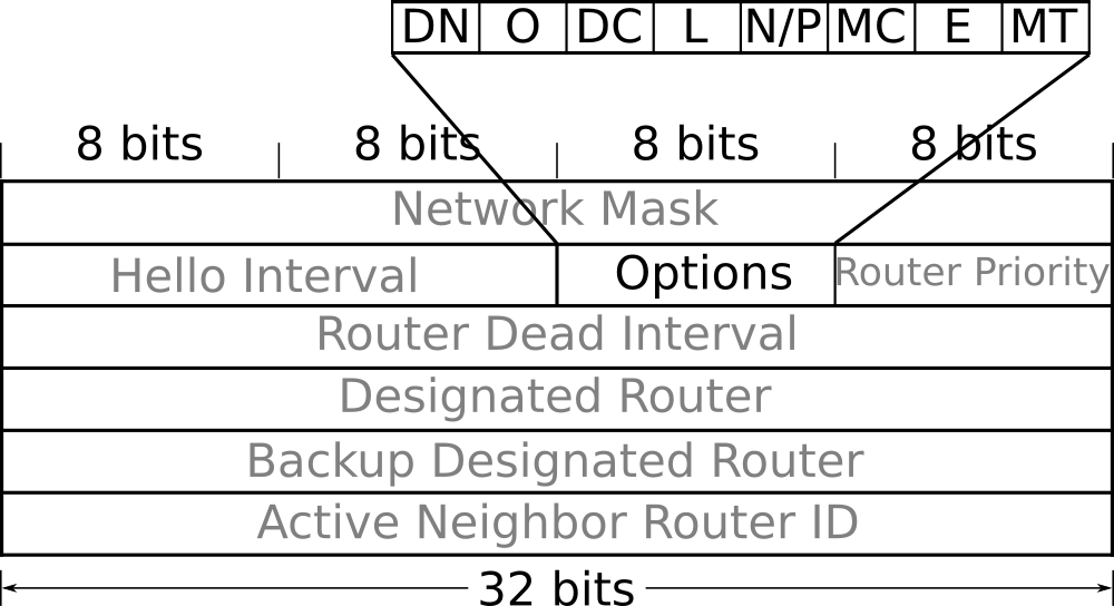
| Bit | Short meaning |
|---|---|
| MT | Multi-Topology |
| E | External routing capability |
| MC | Multicast extension |
| P | Propagate |
| N | NSSA |
| L | Link Local Signaling |
| DC | Demand circuit |
| O | Opaque LSAs |
| DN | Do Not flood |
The paragraphs below describe how OSPF uses the bits in the Options field:
MT: The MT-bit is used to indicate a setting of Multi-Topology Routing in OSPF (MTR). A router may support MTR, yet have the MT-bit cleared due to being configured this way. In Cisco IOS-XE, the MT-bit is set as a result of explicit configuration. The first two OSPFv2 RFCs (RFC 1247 and RFC 1583) actually defined the bit as the T-bit. The T-bit indicated the router’s capability to route using the OSPFv1 concept of TOS-based routing which, although similar to MTR, never saw widespread adoption. Therefore, RFC 2178 deprecated (deleted) the TOS routing option (section G.10).
MT-OSPF is defined in RFC 4915 - Multi-Topology (MT) Routing in OSPF (June 2007). When the MT-bit in the Options field is set, the router may advertise the links attached to it as belonging to several TOS (topologies), without advertising the link belonging to the default (base) topology.
E: The E-bit is the only bit in the Options field that is defined in RFC 2328, and it describes how AS-external-LSAs are handled. In general, it indicates a router’s capability and willingness to process AS-external-LSAs. All Hello messages exchanged within a regular area should have their E-bit set. Hello messages exchanged within a stubby or NSSA area should have their E-bit cleared. A mismatched E-bit in Hellos will prevent the adjacency from coming up, thus enforcing that all routers are consistently configured as either part of a stub area or not. The E-bit is also set in all LSAs associated with non-stub areas, and cleared in all LSAs in a stub or NSSA area. Since AS-external-LSAs do not exist within stub areas, the E-bit is always set in AS-external-LSAs. The other uses of E-bit are discussed in the The many faces of the E-bit section of the LSA Types chapter.
MC: The MC-bit is defined in RFC 1584 - Multicast Extensions to OSPF, which is now in Historic Status. The Multicast Extensions to OSPF never saw much vendor support, and Cisco never implemented RFC 1584.
P: The P-bit is only defined for the Type-7 LSA header. In the NSSA-external-LSA header, it flags whether the external information carried within the LSA should be propagated beyond the NSSA, into the rest of the OSPF routing domain. When set, an NSSA translator is to translate the Type-7 LSA into an AS-external LSA and flood it into the backbone. The P-bit is allocated the same position as the N-bit discussed earlier, but since the two bits are defined for different uses, and in different messages, there is no conflict or ambiguity. Only NSSA translators use the N-bit to make a decision about whether to translate the LSA. The exact algorithm of how OSPF determines when to assign the P-bit and how the P-bit affects various aspects of OSPF design is discussed at great length in the Stub areas chapter.
N: The N-bit is defined only for Hello packets and its sole purpose is to guarantee that all routers in an area agree whether the area is an NSSA area or not. The N-bit must match between neighbors or else they will drop each other’s Hello messages and thus never become neighbors. When a router does not support NSSA functionality, it will not be able to join the NSSA area since it will always keep the N-bit cleared in Hello messages. The N-bit is repurposed as the P bit (discussed next) in Type-7 LSAs within NSSA areas. Since NSSA routers cannot accept and process AS-external-LSAs, the E-bit must be cleared on all Hello messages that have their N-bit enabled. This makes the E and N bits mutually exclusive. RFC 3101 does not define how the N-it should be set in LSA headers or in Database Description headers besides the statement that The N-bit is used only in Hello packets. IOS (in violation of RFC 3101) always sets the N-bit for all LSAs generated within an NSSA (with the exception of Type-7 LSAs that do not have this bit), and in DD packets.
L: The L-bit is set in Hello and Database Description packets when a Link-Local Signaling (LLS) data block is attached to the OSPF message. RFC 5613 - OSPF Link-Local Signaling defines LLS and defines how you can append a block to a regular Hello or Database Description packet. In case the regular packet is authenticated, then the LLS payload is also authenticated, and the authentication data for the LLS data is placed in a separate TLV within the LLS data block. The LLS authentication TLV has a Type value of 2. This bit had originally been defined as the EA bit in RFC 2328, but has since been deprecated. For more information see the LLS section of the OSPF Convergence Optimization & Scalability chapter.
DC: The DC-bit is set by a router in all of the LSAs generated by the router when the router supports the demand circuit (DC) extension of OSPF. The same bit is used in Hello and Database Description packets to negotiate Hello suppression over a link, between two neighbors (which is part of DC operation). The demand circuit options bit was introduced for OSPF in Cisco IOS 11.2 in response to the publication of RFC 1793. A mismatch in the DC bit will not prevent adjacency. What can be configured is for one side to attempt to negotiate a link to be treated as an on-demand circuit, whereas the other side can be configured to explicitly ignore such a request (with the ip ospf demand-circuit ignore command). This feature is discussed in the Demand Circuit section of the Convergence Optimization and Scalability chapter.
O: The O-bit is used only in Database Description packets, and describes the sending router’s capability and willingness to accept and re-flood Opaque LSAs. Opaque LSAs are Type 9, 10, and 11 LSAs, and are defined (along with the O-bit) in RFC 5250 - The OSPF Opaque LSA Option. This bit is only used in the DD header and is not set in Hellos, nor in any LSA header. Since the O-bit is only set in DD packets, it has no effect on any potential adjacency (whether an adjacency comes up depends only on the contents of Hello messages). Opaque LSAs are used in IOS for the Graceful Restart and MPLS-TE features.
DN: The DN bit is used to prevent looping in MPLS IP L3 VPNs. For example, assume Site A redistributing an OSPF route into MP-BGP as part or normal L3 VPN operation. Next, assume that the advertisement reaches a dual-homed Site B, and is redistributed into OSPF at Site B. A router in Site B could redistribute the same prefix back into the provider’s MP-BGP, potentially causing a routing loop. The DN bit is set on all LSAs that are redistributed by an MPLS provider’s MP-BGP into a site’s OSPF LSDB. And when redistributing local information into an MPLS provider’s BGP, an OSPF router will always ignore LSAs that have their DN bit set. Discussions on MPLS, MP-BGP and OSPF as a PE-CE routing protocol are beyond the scope of this book. To better appreciate the problem that the DN bit solves and how it actually goes about solving it, you can read the three RFCs listed in the table below:
| RFC # | Title |
|---|---|
| 4364 | BGP/MPLS IP L3 VPNs |
| 4576 | LSA Options Bit to Prevent Looping in BGP/MPLS IP VPNs |
| 4577 | OSPF as PE-CE protocol for BGP/MPLS IP VPNs |
Router ID
The Router ID in OSPF is a 32-bit identifier, uniquely identifying an OSPF router as a node within an area’s graph, and in the case of Autonomous System Border Routers (ASBRs) even beyond the area boundary. If several nodes use the same Router ID to identify themselves within an area, the SPF algorithm will produce wrong results at most instances and a flooding war will ensue.
Every router originates several LSAs within an OSPF domain. Of those LSAs, some describe the router itself and its directly attached networks, and some describe networks the router can reach.
Every LSA has the Advertising Router field, populated with the Router ID of the router generating the LSA.
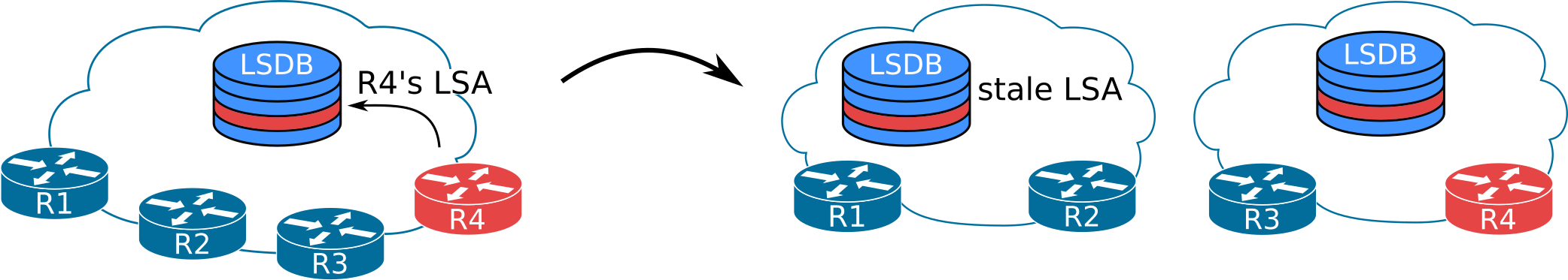
In the scenario shown above we can see how a partition of the network creates two not-synchronized versions of the same LSDB. Each LSDB holds its share of stale LSAs. Stale LSAs are not used for SPF calculations but are still stored within the LSDB until they age out.
R4’s LSA on the left partition of the LSDB is not necessarily inaccurate. If, while the network is partitioned, R4 does not modify or retract any of its LSAs, then both LSAs will actually hold valid information.
Now consider what will happen if the state of any of R4’s links changes while the LSDB is partitioned. The right-hand-side of the LSDB will contain the fresh and valid R4’s LSA, while the stale LSA will contain the old, no-longer-valid information.
When the network is reunited, the LSDB has to be synchronized across all routers.
The way to do this will be for each router to verify that all LSAs originated by itself contain valid information.
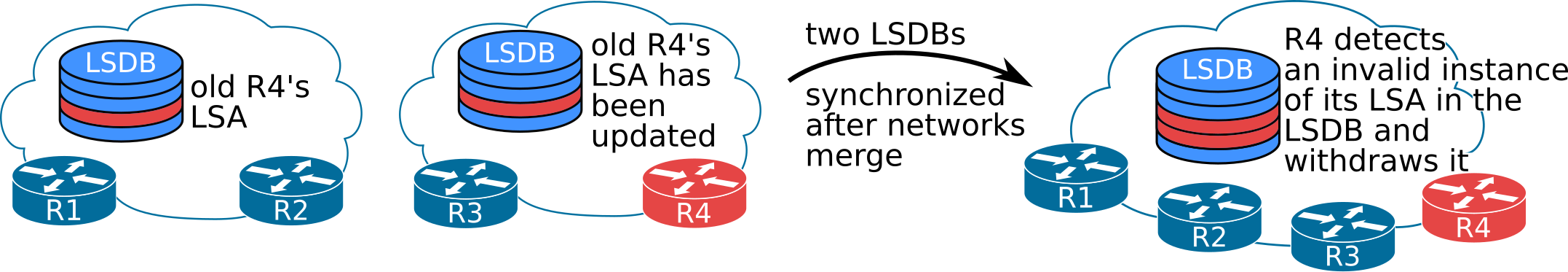
Once R4 detects the stale LSA in the LSDB, it will poison it. R4 will do this by inserting a record into the LSDB with an age of MaxAge. This way the record (LSA) will be deleted from the LSDB due to the aging mechanism.
Due to the manner by which the LSDB is synchronized across an OSPF area (as described in the above example), a router may sometimes receive an LSA that is no longer valid but the router has itself generated some time earlier. The router will receive such a stale LSA during the LSDB synchronization process.
When a router detects an LSA sourced by itself (with its own Router ID in the Advertising Router field) in the LSDB that it feels to be invalid, it designates such an LSA as stale. The router will then generate a new LSA to replace and correct the stale information in the area’s LSDB. This behavior is called OSPF’s fight-back mechanism and serves a twofold purpose:
- It is a a reliable way to flush out any LSAs a router has originated earlier with the newest possible information.
- It also functions as a robust security mechanism.
A visualization of the events and LSAs sent out in an effort to synchronize the LSDB after a partition event is shown below:
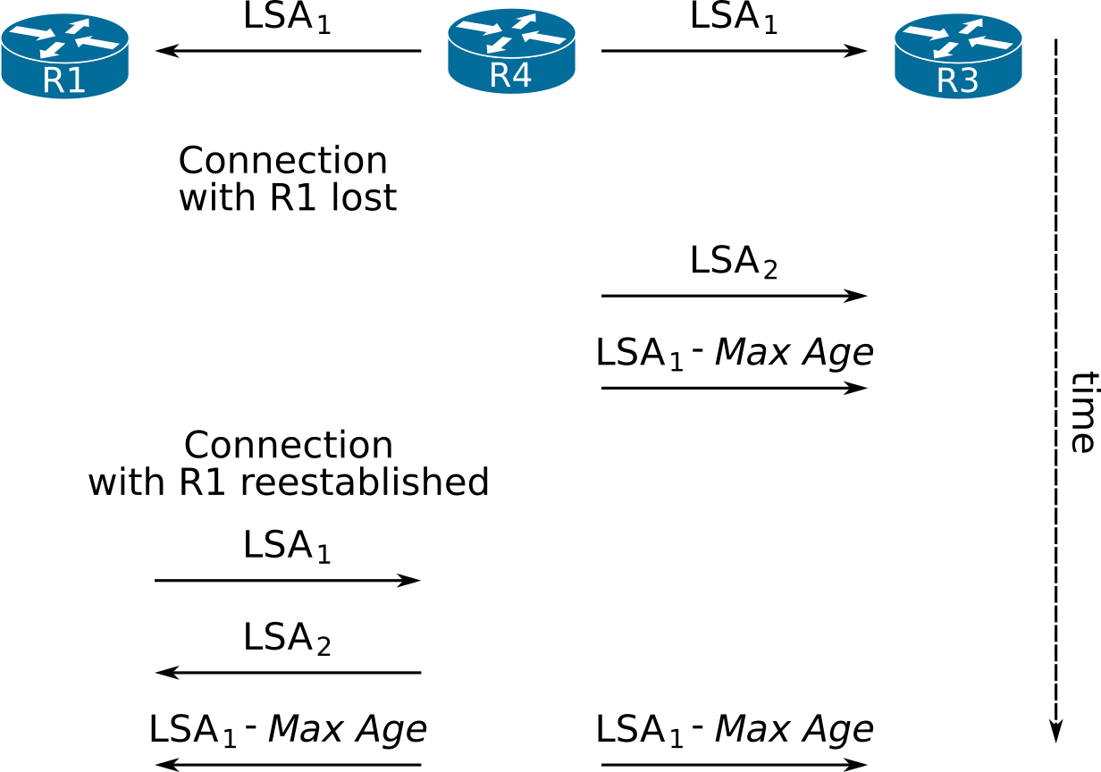
In the timeline above, R4 starts by sending out LSA1 to all its neighbors, essentially inserting a record into the LSDB. At some point, R1 gets disconnected from R4 and R3 and retains LSA1 until it expires in its local copy of the LSDB. During this time, something changes at R4 and so R4 issues a new LSA (LSA2) to replace LSA1, and as a result it withdraws LSA1. As usual, to withdraw an LSA a router generates the LSA with MaxAge.
Later, connectivity is reestablished from R4 to R1. During the initial LSDB synchronization R1 sends LSA1 to R4 (which was still in R1’s copy of the LSDB). This triggers R4 to poison the stale LSA1 from the LSDB. To this effect, R4 will send out LSA1 with a MaxAge to all its neighbors. The poisoned LSA1 is also sent out to R3 because R1 cannot be certain that the stale LSA1 did not reach R3 through some other R1-R3 path. To guarantee that the stale LSA is flushed throughout the entire LSDB, OSPF dictates that each LSA (poisoned or otherwise) is flooded into all directions.
A router verifies whether the received LSA is an LSA that it has indeed originated by checking only two fields:
- The LSA’s sequence number must be equal to the latest sequence number that was issued by the router for the particular LSA.
- The LSA’s checksum must match the checksum of the local copy of the LSA generated by the router.
The router will not check or verify the remaining contents of the LSA if the two above fields are correct. Since the OSPF security fight-back mechanism relies heavily on the results of these checks, the design choice to not verify the LSA contents (beyond the sequence number and checksum), combined with the computational simplicity of the checksum algorithm, have led to successful attacks against OSPF infrastructure. The easiest mitigation technique against these attacks is to deploy TTL security and authentication. Attacks on OSPF and TTL security are discussed in further detail in the Security chapter (coming soon).
The designers of OSPF cannot be rightfully blamed for this design choice because at design time, the OSPF packet checksum would protect the packet’s payload from in-flight data corruption and the LSA checksum protects against in-memory corruption. Neither of the two checksums was ever meant to be used as a security mechanism to detect malicious LSA generation and injection. Furthermore, the computational complexity of the checksum algorithms was intentionally selected to be the lowest possible in order to accommodate the underpowered processors that OSPF was designed to run on, at the time.
A bigger problem that will arise from duplicate Router IDs is when the router originates an LSA describing a network. These can be type 2, 3, 5, or Type-7 LSAs. Assume for the sake of our discussion an ABR, having a duplicate Router ID as another router in an area it is attached to, and the Border router generates a network summary-LSA. The LSA will be propagated normally throughout the area, and it will reach the router that did not generate the LSA, and has no knowledge of how to reach the advertised network. Once the router receives an LSA which it believes has been originated by itself, it will examine whether the LSA is valid and accurate. When the router realizes that it cannot reach the advertised network, it will assume that the particular LSA is a leftover LSA from a previous life, a life where the router could reach the network. Since this is not the case anymore, the router has an obligation to let everyone know that the LSA is no longer valid, by prematurely flushing the LSA. Premature flushing of an LSA from the routing domain is achieved by setting its LS age to MaxAge, while leaving its LS sequence number alone, and then reflooding the LSA. If any LSA’s LS age reaches MaxAge (either naturally within a process’s local LSDB or after receiving the LSA), it is removed from the local copy of the LSDB. The same behavior holds true for an ASBR generating a type 5 or 7 LSA into an area with another internal router that has a duplicate Router ID.
- MaxAge
- The maximum age an LSA can attain within the LSDB (in seconds) before being flushed. Defined in RFC 2328 - OSPF v2, Appendix B as 1 hour (3600 seconds).
As soon as the other router (the true originator) notices its LSA MaxAged, it will regenerate the LSA, endlessly. This vicious cycle is called a flooding war, and the IOS routers that participate in this flooding war will generate the SYSLOG message FLOOD_WAR.
When an OSPF process starts up, it needs a Router ID. If no IP address is configured on an active interface, and no Router ID is otherwise explicitly configured, the OSPF process fails to start. The following CLI output shows the SYSLOG message when OSPF fails to start because it cannot find a Router ID.
Even though an IP address is configured for interface Ethernet0/3, since the interface is administrative down, OSPF cannot pick it up and thus fails to initiate.
Router ID name-lookup
The Router ID is a 32-bit number identifying OSPF routers. In the outputs of show commands on the CLI, the Router ID is usually displayed in a dotted decimal notation, e.g. 192.1.1.1.
When managing a larger network with many OSPF routers, remembering each Router ID becomes cumbersome. To alleviate some of the administrator’s burden, Cisco implemented the Router ID name-lookup feature to replace Router IDs in the output of show commands with router hostnames.
To configure Router ID to router hostname resolution for use within show command output, use the ip ospf name-lookup global configuration mode command:
The ip ospf name-lookup command forces IOS to resolve Router IDs to names, and it can be utilized using one of two deployment methods:
- Locally defined Router-ID-to-name association
- Centralized DNS
Each deployment method has its trade-offs:
- When using a locally defined Router ID/name association:
- The Router ID lookup will be faster than querying a remote DNS server
- The association will always be available, even if the DNS server is not
- The Router ID can be any arbitrary 32-bit number (0.0.0.1 or 127.255.255.0 for example)
- Using a centralized DNS service to resolve a Router ID to the router’s hostname:
- Allows for easier Router-ID-to-hostname changes, at a centralized location. Once the change is in effect at the DNS server, all routers resolving Router IDs using DNS will be able to resolve to the new hostname, without the need for any changes in local configuration. A single change at a central location will thus have global effect.
- Makes additions of new associations easier (this is especially significant in larger networks)
- Lowers the configuration burden per router, and requires lower configuration management burden than using manual Router ID-to-name associations.
- Requires that the Router ID of each router be a reachable IP address within the network, since other services might also need to resolve the router’s name to an IP address (Ansible or a monitoring system for example).
To define local Router-ID-to-hostname associations, use the ip host R2 2.2.2.2 command, where R2 is the router’s hostname, and 2.2.2.2 is the Router ID.
To use a centralized DNS server to resolve the OSPF neighbor’s hostname, a DNS server must be configured on the router, and name lookup should also be globally enabled:
If there is no local route to the configured DNS server, the configuration will essentially be ignored. If, on the other hand, a DNS server is configured and a route to the server exists but the server either does not respond, or has no entry for the Router ID, the show ip ospf commands will appear to hang. IOS will be waiting for a response (in the order of 10-20 seconds) before displaying the output of the commands without having resolved the Router IDs.
Once Router ID name-lookup is enabled, the CLI output will then become easier to parse visually, as can be seen in the CLI output below.
As we can see, the name-lookup function is not absolutely necessarily in a small environment but becomes a real time saver in larger deployments.
For reference purposes, below you can find the commands to configure an IOS router to act as a DNS server.
More information on what each of the above commands does and on how to configure IOS for DNS services can be found at DNS Configuration Guide, Cisco IOS Release 15M&T.
1.5 Basic configuration
Using the network statement
The network statement is the classic way to enable OSPF on a set of interfaces.
The network ip-address wildcard-mask area area-id OSPF router subcommand works using the following algorithm:
- The router applies the ip-address wildcard-mask arguments as an ACL, in order to figure out which interfaces match. The next steps are applied only for the matching interfaces.
- The router adds the networks connected to the matching interfaces to its OSPF LSDB for area area-id
- As a consequence of this second step, the router generates a new router-LSA advertising the networks connected on/to the interfaces to all of its current OSPF neighbors in area area-id
- The router sends OSPF Hello messages out of the matched interfaces trying to find neighbors belonging in area-id
Using the following topology as a reference:

Let us assume for example’s sake that an administrator configures the following command on R1:
network commandThen applying the logic described above, IOS on R1 will perform the following steps:
- R1 will apply 10.0.0.0 0.1.255.255 as an ACL on all of the IP addresses configured on its interfaces. These are:
- 10.2.2.1
- 10.1.1.1
- 10.0.12.6
- 10.0.13.17
- 10.0.14.2
- After applying the ACL, IOS knows which interfaces match, so it will apply the actions of the next steps. In R1’s case, interfaces G0/1, G0/2, G0/3, and G0/4 match.
- R1 adds the networks attached to the matched interfaces to its Area 0 LSDB:
- 10.1.1.0/24
- 10.0.12.4/30
- 10.0.12.16/30
- 10.0.13.0/30
- R1 will send out an updated router-LSA for R1, (now containing the networks added in the previous step) as networks directly attached to R1.
- R1 sends OSPF Hello messages out of the matched interfaces (G0/1, G0/2, G0/3 and G0/4) looking for neighbors belonging to Area 0.
Note that in older versions of IOS, the network commands are processed in sequential order, and later commands do not override earlier ones. Consider the following configuration:
The above configuration would (in some very old IOSs) actually add interface 192.168.1.2 to area 0, event though the second network command is more specific than the first one. Whichever network command got an interface first got it forever, even if subsequent network commands would assign the interface to another area. Since at least IOS 12.1, the same general rule is applied, only with a (quite sane) twist. When entering the various network command in newer IOS versions, the CLI sorts them by wildcard mask length, in ascending order, enters them into the running config in that order, and then applies the network commands sequentially.
This sorting and then applying of network commands is more intuitive than the earlier behavior. Furthermore, to ease the transition of this behavior from older versions, IOS now generates a SYSLOG message whenever a newly entered network command overrides an already existing network command that has already assigned an interface to an area.
To verify that an interface has OSPF enabled on it use the show ip ospf interface command, and look for the Attached via Network Statement phrase.
In Routing TCP/IP, Volume 1, 2nd Edition by Jeff Doyle and Jennifer Carroll, the following passage appears:
When the OSPF process first becomes active, it will “run” the IP addresses of all active interfaces against the (address, inverse mask) pair of the first
networkstatement. All interfaces that match will be assigned to the area specified by theareaportion of the command. The process will then run the addresses of any interfaces that did not match the firstnetworkstatement against the secondnetworkstatement. The process of running IP addresses againstnetworkstatements continues until all interfaces have been matched or until all network statements have been used. It is important to note that this process is consecutive, beginning with the firstnetworkstatement. As a result, the order of the statements can be important, as is shown in the troubleshooting section.
I did not manage to confirm the described behavior with any IOS version from 12.0(5)T1 upward, so be wary.
The earliest IOS that I am aware of that does not re-sort network commands before adding them to the running-config is IOS 12.0, which instead rejects any more specific network commands than any commands already configured.
network command if a less specific command is already in the running-configSecondary addresses
If a network command matches a secondary address, but the interface’s primary IP address is not matched by any network command, then the match on the secondary address is not acted upon. So, if an interface has a secondary address of 192.168.0.2/24, but the interface’s primary IP address of 10.0.23.2/24 is not matched by the network 192.168.0.2 0.0.0.255 area 0 command, no IP subnet off the interface will have OSPF enabled on it.
network command should match both an interface’s primary and secondary addressesThe above configuration steps will not configure OSPF to send any Hello messages out of interface Eth0/1, nor will network 192.168.0.0/24 be advertised into the OSPF domain. Only after the primary IP address is matched by a network command (network 10.0.23.0 0.0.0.255 area 0 for example), will OSPF start sending Hellos from the Eth0/1 interface, sourcing all of its communication from the primary IP address, and advertising any secondary IP networks into the OSPF domain, so long as the secondary address is also covered by a network statement.
If, on the other hand, only the network 10.0.23.2 0.0.0.0 area 0 command were present (and network 192.168.0.2 0.0.0.255 area 0 was missing), IOS would not advertise the secondary subnet into OSPF.
As far the source IP address of OSPF packets is concerned, IOS will not under any circumstances source an OSPF packet using a secondary IP address, and will not process any packets destined to a secondary address.
Secondary subnets are always advertised as stub networks attached to Router LSAs.
In the IOS output above, 10.0.23.0/24 is the primary IP network on the Ethernet 0/1 interface and 192.168.0.0/24 is the secondary IP network on the same interface.
To advertise a secondary subnet into OSPF using the network command, issue a network command to cover both the primary and secondary IP addresses configured on an interface, or two separate network commands that should match both the primary and secondary IP addresses. OSPF has to be enabled for the primary IP address (using either the network or the ip ospf area commands), otherwise the secondary IP address will not be advertised into OSPF, regardless of any network commands that might cover it.
Interface Statement
Another way to enable OSPF on an interface is to use the ip ospf <PID> area <area-ID> interface configuration command. Issuing this command will advertise the IPv4 network(s) (subnet(s)) attached to an interface into OSPF, and will also start sending OSPF Hello messages looking for OSPF neighbors off that interface.
By default, once OSPF is enabled on an interface by the ip ospf area command, OSPF is enabled for all networks attached to the interface, primary and secondary as well. This can be verified by the output of the show ip ospf interface command:
If you don’t need to advertise the secondary networks into OSPF, a variation of the ip ospf area command can be used:
There is no way to only advertise a subset of the secondary addresses using the ip ospf area command. If such granularity is useful, the network command is more flexible in this sense. An example of enabling OSPF only for the primary IP address of an interface:
The secondaries none wording was used instead of potentially no-secondaries because the IOS designers were keeping in mind the possibility of adding something like an ACL filter (in future IOS releases) as an alternative to the blanket none.
OSPF Configuration in IOS-XR
IOS-XR seems to be the direction in which Cisco is moving to create a unified and consistent CLI and configuration method. In particular, IOS-XR keeps all of the routing protocol’s configuration within a single section. The trend to contain all of a specific routing protocol’s configuration within a configuration section in IOS appears in the newer Address-Family configuration methods for EIGRP and OSPFv3.
An example of configuring OSPF on IOS-XR, along with the various configuration modes and sub-modes, is shown below:
1.6 OSPF Finite State Machine
The OSPF Finite State Machine (FSM) describes the various stages and states of a neighborship with another OSPF neighbor. This FSM is maintained on a per-neighbor basis. The OSPF FSM is shown below for reference purposes.
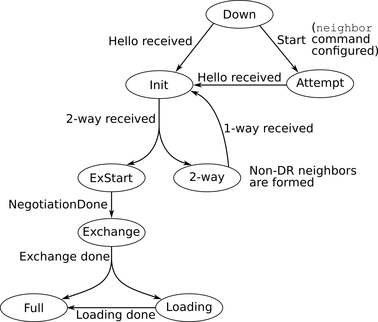
The OSPF FSM as drawn above is essentially a verbatim reprint from RFC 2328, Figures 12 and 13. A more detailed explanation of the various events and states is offered in the same section, section 10.1 of RFC 2328.
1.7 References
- OSPF show Commands Respond Slowly
- Reverse lookup of OSPF Router IDs
- RFC 5243 - OSPF Database Exchange Summary List Optimization
- The OSPF Options Field
- OSPF Support for MTR
- Multi-Topology Routing in OSPF
- IP Routing: OSPF Configuration Guide, Cisco IOS Release 15M&T, OSPF Per-Interface Link-Local Signaling
- OSPF Nonstop Forwarding (NSF) Awareness
- High Availability Configuration Guide, Cisco IOS Release 15SY - Configuring NSF-OSPF
- Troubleshooting Duplicate Router IDs with OSPF
- The War is On Between R4 and SW4!